
Vehicle tire wear detection device and method and vehicle control system

A vehicle control system and detection equipment technology, which is applied to vehicle parts, tire parts, transportation and packaging, etc., can solve the problems of high cost, susceptibility to external interference, tire blowout, etc., and achieve the effect of strong practicability and accurate measurement

Active Publication Date: 2018-08-03
GREAT WALL MOTOR CO LTD
View PDF6 Cites 0 Cited by
  • Summary
  • Abstract
  • Description
  • Claims
  • Application Information

AI Technical Summary

Problems solved by technology

[0003] However, this method in the prior art has the following disadvantages: 1. The resistance wire or electrical components installed inside the tire will cause uneven loads around the tire, thereby making the dynamic balance effect worse; 2. If the resistance wire or electrical components installed inside the tire The resistance wire or electrical components are damaged and cannot be repaired, but the tire can only be replaced as a whole, which also causes a lot of unnecessary waste; 3. The resistance wire or electrical components are embedded in the tire. Due to the particularity of the rubber material of the tire, it will The strength of the embedded resistance wire or electrical components of the tire will deteriorate, which will seriously affect the service life of the tire. Under extreme working conditions, a tire may burst, which seriously affects the safety of driving; 4. The signal transmission is extremely Difficult to implement, while the reliability of wireless transmission is poor, the cost is high, and it is susceptible to external interference

Method used


Image

  • Vehicle tire wear detection device and method and vehicle control system
  • Vehicle tire wear detection device and method and vehicle control system
  • Vehicle tire wear detection device and method and vehicle control system

Examples


Embodiment Construction

[0037] It should be noted that, in the case of no conflict, the embodiments of the present invention and the features in the embodiments can be combined with each other.

[0038] In addition, the vehicle under load mentioned in the embodiments of the present invention means that the vehicle is under load. The curb weight of the vehicle mentioned in the embodiments of the present invention refers to the condition that the vehicle is unloaded. In addition, those skilled in the art should understand that the wheel cover is a part of the vehicle body.

[0039] The present invention will be described in detail below with reference to the accompanying drawings and examples.

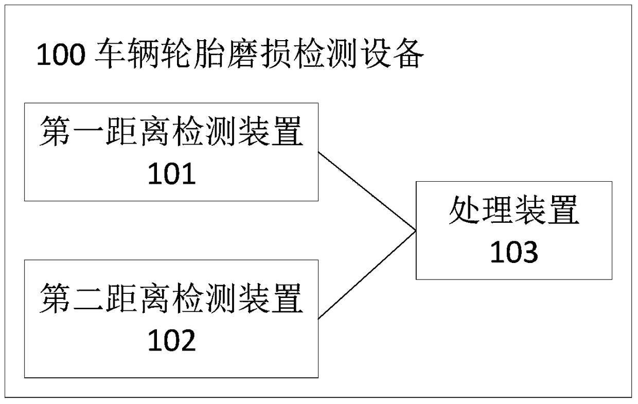
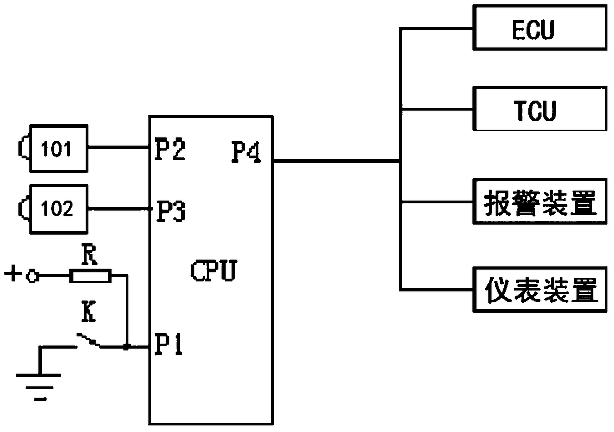
[0040] figure 1 It is a block diagram of the vehicle tire wear detection device 100 described in the embodiment of the present invention, as figure 1 As shown, the vehicle tire wear detection device 100 includes a first distance detection device 101 , a second distance detection device 102 and a processing d...


PUM


Abstract

The invention relates to the field of vehicle tire wearing detection, and provides vehicle tire wearing detection equipment and a method and a vehicle control system. The vehicle tire wearing detection equipment comprises a first distance detection apparatus used for measuring the distance between tire and a wheel cover of the vehicle; a second distance detection apparatus used for measuring the distance between a suspension and a body of the vehicle; a processing apparatus wherein, the practical distance of the suspension and the tire is obtained according to the measured distance between the tire and the wheel cover under vehicle load, and the tire wear extent is calculated according to the practical distance between the suspension and the tire and the initial distance between the suspension and the tire under vehicle kerb mass; and an alarm apparatus used for alarming according to tire wear extent. The technical scheme of the vehicle tire wearing detection equipment is characterized in that under condition of no change of a tire structure, the vehicle tire wearing condition is automatically calculated, and driving safety can be guaranteed by controlling the driving speed according to the tire wear extent.

Description

technical field [0001] The invention relates to the technical field of vehicle tire wear detection, in particular to a vehicle tire wear detection device and method and a vehicle control system. Background technique [0002] At present, the commonly used method to detect the wear of vehicle tires is to install resistance wires or electrical components inside the tires. When the tires are worn out, the resistance wires or electrical components will also be worn, so the change of the resistance value of the resistance wires or electrical components can be used. To obtain tire wear. [0003] However, this method in the prior art has the following disadvantages: 1. The resistance wire or electrical components installed inside the tire will cause uneven loads around the tire, thereby making the dynamic balance effect worse; 2. If the resistance wire or electrical components installed inside the tire The resistance wire or electrical components are damaged and cannot be repaired,...

Claims


Application Information

Patent Timeline
Patent Type & Authority Patents(China)
IPC IPC(8): B60C19/00
CPCB60C19/00B60C2019/006
Inventor 董伟佳杨志广张铁群李增奎
Owner GREAT WALL MOTOR CO LTD
Learn More