Semi-automatic proofing punching and marking-out instrument, punching machine and using method

A semi-automatic, sample punching technology, applied in the direction of striking tools, manufacturing tools, center blunderbuss, etc., can solve the problems of scrapping, inaccessibility of center drills, and inability to form workpieces, etc., and achieves strong operability, high safety, and simple structure Effect

Pending Publication Date: 2017-05-10
ANQING CSSC DIESEL ENGINE
View PDF8 Cites 4 Cited by
  • Summary
  • Abstract
  • Description
  • Claims
  • Application Information

AI Technical Summary

Problems solved by technology

When spot drilling a large workpiece with a group of holes distributed on the blank, because the surface of the blank is uneven and the surface is not perpendicular to the spindle of the machine tool, it is difficult to determine the safety distance and spot drilling depth when programming the drilling cycle CNC program
If the spot drilling depth value is set larger, the spot drilling depth may be too deep. When the hole position is wrong, the deeper spot drilling holes will not be covered and cause workpiece defects or even be scrapped; if the spot drilling depth value is set smaller, It is possible that the center drill cannot touch the workpiece and the center hole cannot be formed
In addition, for some workpieces, it is necessary to mark the line on the machine tool, but because the surface of the blank is uneven, if the line is marked with an ordinary thimble, the lines on the surface of the blank will be of different depths, and at the same time, the wear of the thimble will be aggravated

Method used


Image

  • Semi-automatic proofing punching and marking-out instrument, punching machine and using method

Examples


Embodiment Construction

[0019] The embodiments of the present invention are described in detail below. This embodiment is implemented on the premise of the technical solution of the present invention, and provides a detailed implementation manner and a specific operation process, but the protection scope of the present invention is not limited to the following implementation. example.

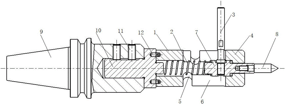
[0020] like figure 1 As shown, a semi-automatic proofing, punching and scribing tool of this embodiment includes a sleeve 1, a spring 2, a handle 3, a stopper, a top cap 4, and a punching piece; the spring 2 is sleeved on the In the sleeve 1, a through hole is opened in the top cap 4, one end of the punching member is connected to the spring 2, the other end is sleeved in the through hole of the top cap 4, and the handle 3 is connected to the punching hole. The two ends of the limiter are respectively connected to the sleeve 1 and the top cap 4, the limiter is axially provided with a through slot for the punching par...


PUM


Abstract

The invention discloses a semi-automatic proofing punching and marking-out instrument, a punching machine and a using method. The instrument comprises a sleeve, an elastic piece, a pull handle, a limiting piece, a top cap and a punching piece. The elastic piece is arranged in the sleeve in a sleeved mode; a through hole is formed in the top cap; one end of the punching piece is connected with the elastic piece, and the other end of the punching piece is arranged in the through hole of the top cap in a sleeved mode; the pull handle is connected on the punching piece; the two ends of the limiting piece are connected with the sleeve and the top cap correspondingly; the limiting piece is provided with a through groove used for sliding of the punching piece and the pull handle in the axial direction; and the limiting piece is provided with an annular groove for clamping and holding the pull handle in the radial direction. The structure is simple, usage is convenient, and the instrument can be mounted on a numerically-controlled machine tool. By means of a spring type proofing dotting-punch instrument, punching and dotting-punch can be realized through manual operation under the condition that a hole site program is written in advance, and meanwhile, the instrument can further be used for blank surface marking out, the safety is high, and the operability is strong.

Description

technical field [0001] The present invention relates to a kind of equipment used for the drilling position of center drilling point, in particular to a semi-automatic proofing, punching and scribing tool, punching machine and using method. Background technique [0002] Before the holes can be machined by the CNC machine, the drill bits need to be drilled through the center drill point. When spot drilling a large workpiece with a group of holes distributed on the blank, it is difficult to determine the safety distance and spot drilling depth when writing the drilling cycle numerical control program because the surface of the blank is uneven and the surface is not perpendicular to the machine tool spindle. If the spot drilling depth value is set larger, the spot drilling depth may be too deep. When the hole position is wrong, the deeper spot drilling will not be covered, resulting in workpiece defects or even scrapping; if the spot drilling depth value is set smaller, Then th...

Claims


Application Information

Patent Timeline
Patent Type & Authority Applications(China)
IPC IPC(8): B25D5/02B25H7/04
CPCB25D5/02B25H7/04
Inventor 邓斌斌齐勇苏寒杨华兵
Owner ANQING CSSC DIESEL ENGINE
Why Eureka
Try Eureka