Double-tool-magazine machining center

A machining center and double tool magazine technology, applied in metal processing equipment, metal processing mechanical parts, manufacturing tools, etc., can solve the problems of reduced work efficiency and slow tool change.

Active Publication Date: 2017-05-10
浙江速成精密机械有限公司
View PDF5 Cites 7 Cited by
  • Summary
  • Abstract
  • Description
  • Claims
  • Application Information

AI Technical Summary

Problems solved by technology

[0002] Existing milling machines usually have only one tool magazine. When changing tools, the manipulator of the tool magazine can only grab one tool at a time, and first clamp the used tool on the spindle of the milling machine and put it on the tool magazine chain. Then clamp the unused tool in the tool pocket of the tool magazine chain, and finally put it on the spindle of the milling machine. If the milling machine processes multiple workpieces at the same time, the manipulator must reciprocate several times every time the tool is changed. To complete the tool change, the tool change speed is slow, reducing work efficiency

Method used


Image

  • Double-tool-magazine machining center
  • Double-tool-magazine machining center
  • Double-tool-magazine machining center

Examples


Embodiment Construction

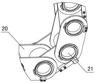
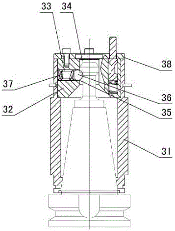
[0021]The present invention relates to a machining center with double tool magazines, as shown in Fig. 1-Fig. The cross slide 85 is set on the rail, the lower end of the cross slide is matched with the Y-direction screw, and the Y-direction screw is driven to rotate by power. The X-direction line rail 86 and the X-direction screw 87 are set on the cross slide. Table 88, the lower end of the workbench cooperates with the X-direction screw 87, the X-direction screw is driven to rotate by power, the workpiece is set on the workbench, the column screw 89 is set in the column 84, and the lifting block 90 is set on the column screw to lift Block front side connects main shaft box 91, is provided with main shaft servomotor 92 and 4-8 with main shaft 93 on main shaft box, the output shaft of main shaft servo motor connects two main shaft belt pulleys 94 up and down, main shaft driven wheel 95 is set respectively on each main shaft, up and down Two main shaft pulleys 94 respectively dr...


PUM


Abstract

The invention relates to a double-tool-magazine machining center. The double-tool-magazine machining center is characterized in that the double-tool-magazine machining center comprises a milling machine body, the milling machine body is provided with a Y-direction linear rail, a Y-direction screw and a standing column, wherein the Y-direction linear rail is provided with a cross slide plate, the lower end of the cross slide plate is matched with the Y-direction screw, the Y-direction screw is driven to rotate by power, the cross slide plate is provided with an X-direction linear rail and an X-direction screw, a working table is arranged on the X-direction linear rail, the lower end of the working table is matched with the X-direction screw, the X-direction screw is driven to rotate by power, a workpiece is arranged on the working table, a standing column screw is arranged in the standing column and provided with a lifting block, the front side of the lifting block is connected with a spindle box, a spindle servo motor and 4-8 spindles are arranged on the spindle box, the output shaft of the spindle servo motor is connected with an upper spindle belt wheel and a lower spindle belt wheel, a spindle driven wheel is arranged on each spindle, the upper spindle belt wheel and the lower spindle belt wheel drive 2-4 spindle driven wheels to rotate through spindle belts, a left tool magazine is arranged on the left of the standing column, a right tool magazine is arranged on the right of the standing column, and each of the left tool magazine and the right tool magazine comprises a transmission conveying device, a milling tool storage and fixing device and a milling tool clamping and conveying device.

Description

technical field [0001] The invention relates to a machining center, in particular to a machining center with double tool magazines, which is mainly used for milling machines. Background technique [0002] Existing milling machines usually have only one tool magazine. When changing tools, the manipulator of the tool magazine can only grab one tool at a time, and first clamp the used tool on the spindle of the milling machine and put it on the tool magazine chain. Then clamp the unused tool in the tool pocket of the tool magazine chain, and finally put it on the spindle of the milling machine. If the milling machine processes multiple workpieces at the same time, the manipulator must reciprocate several times every time the tool is changed. To complete the tool change, the tool change speed is slow and the work efficiency is reduced. Contents of the invention [0003] The purpose of the present invention is to overcome the shortcomings of the prior art, and provide a machin...

Claims


Application Information

Patent Timeline
Patent Type & Authority Applications(China)
IPC IPC(8): B23Q3/157
CPCB23Q3/1552B23Q3/15766B23Q3/15773B23Q3/15539
Inventor 应云富
Owner 浙江速成精密机械有限公司
Why Eureka
Try Eureka