
Flexible guide rail welding robot

A welding robot, flexible guide rail technology, applied in welding equipment, auxiliary welding equipment, welding/cutting auxiliary equipment, etc., can solve the problems of unstable welding accuracy, high risk factor, large workload, etc. The welding position is accurate and the effect of improving the welding accuracy

Active Publication Date: 2017-05-10
CHENGDU NANFANG ELECTRONICS METER CO LTD
View PDF9 Cites 9 Cited by
  • Summary
  • Abstract
  • Description
  • Claims
  • Application Information

AI Technical Summary

Problems solved by technology

[0006] The purpose of the present invention is to solve the problem that welding robots in the prior art cannot perform welding operations on large-scale arc surface equipment such as steel spherical tanks, storage tanks, and ship hulls, and when manually performing arc surface welding operations on large workpieces, it is often necessary to use ladders and slings Such as climbing operation tools, heavy workload, high risk factor, and unstable welding accuracy. A flexible guide rail welding robot is provided. Through the flexible guide rail with adjustable position, the device can control the movement of the device on the surface of large arc welding workpieces, and complete the whole process. Azimuth Arc Welding Operations

Method used


Image

  • Flexible guide rail welding robot
  • Flexible guide rail welding robot
  • Flexible guide rail welding robot

Examples


Embodiment 1

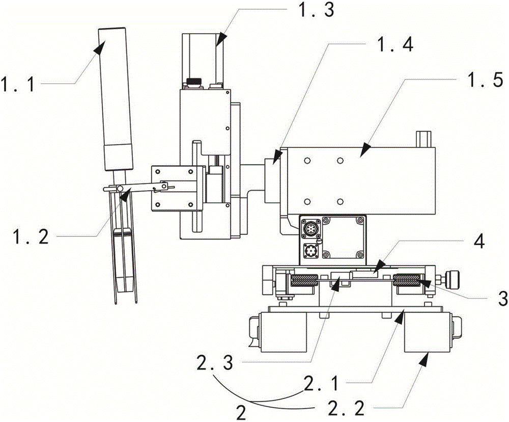
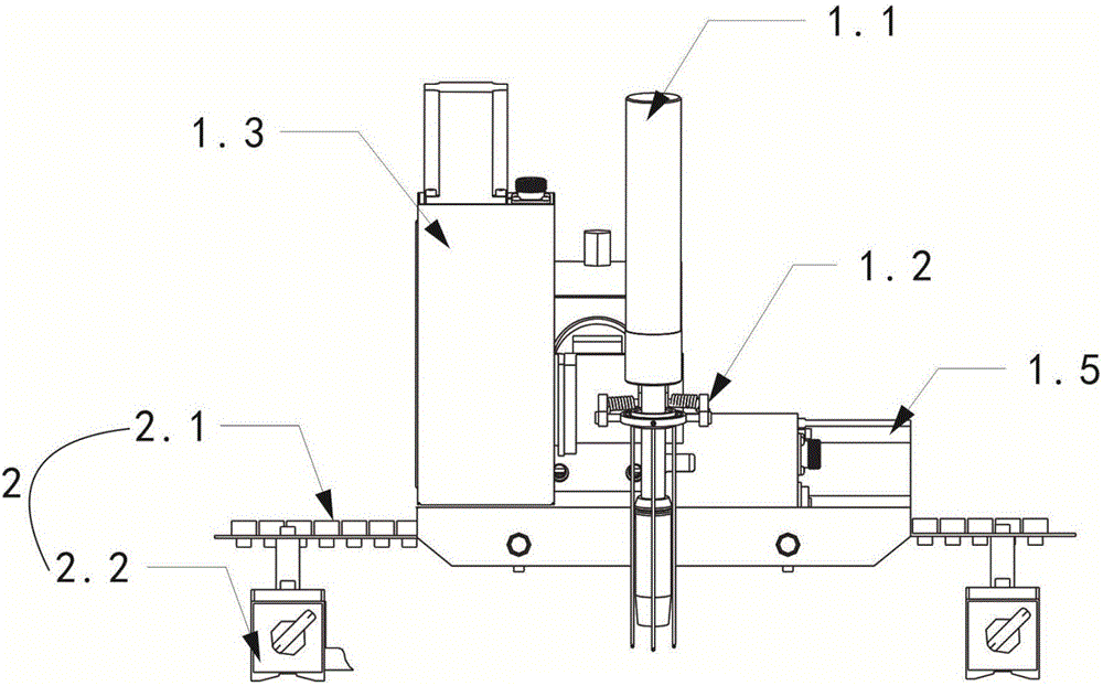
[0032] Embodiment 1, a welding robot with flexible guide rails, including a welding main body (1) for controlling welding actions and a track device (2) for absorbing on the surface of a welding workpiece, the welding main body (1) is placed on the track device (2) ); the track device (2) includes a flexible guide rail (2.1) and magnetic seats (2.2) evenly distributed on the bottom of the flexible guide rail (2.1), and the magnetic seats (2.2) are adsorbed on the surface of the welding workpiece.

[0033] The flexible guide rail welding robot of this embodiment also includes a main drive wheel (3) for driving the movement of the welding main body (1) and a guide wheel (4) for turning, and the main drive wheel (3) is elastically connected The piece (8) is connected with the flexible guide rail (2.1), and the guide roller (4) is meshed with the flexible guide rail (2.1) through the gear (2.3). Further, the flexible guide rail welding robot also includes a DC deceleration motor a...

Embodiment 2

[0035] Embodiment 2 is optimized as follows on the basis of Embodiment 1: the welding main body (1) includes a welding torch (1.1), a welding torch clamp (1.2), a height adjustment mechanism (1.3), an angle adjustment mechanism (1.4) and a lateral adjustment mechanism ( 1.5); the welding torch (1.1) is fixed on the welding torch clamp (1.2), and one end of the welding torch clamp (1.2) is connected to the height adjustment mechanism (1.3) that controls the welding height position, and one end of the height adjustment mechanism (1.3) is connected to An angle adjustment mechanism (1.4) for controlling the welding angle is connected, and the angle adjustment mechanism (1.4) is connected with a horizontal adjustment mechanism (1.5) for controlling the left and right movement of the welding torch (1.1).

[0036]In this embodiment of the flexible guide rail welding robot, the horizontal adjustment mechanism (1.5) and the height adjustment mechanism (1.3) both include a swing motor, a...

Embodiment 3

[0038] Embodiment 3 On the basis of Embodiment 1 or 2, the following optimizations are made: the flexible rail welding robot of this embodiment also includes a remote control device and a sensor (7) arranged on the robot main body (1), and the remote control device passes through The sensor (7) realizes information interaction with the robot main body (1). The operator controls the welding operation of the robot in real time through the remote control device to realize human-computer interaction.


PUM


Abstract

The invention discloses a flexible guide rail welding robot which comprises a welding main body (1) for controlling welding operation and a rail device (2) adsorbed on the surface of a welding workpiece, wherein the welding main body (1) slides on the rail device (2); the rail device (2) comprises a flexible guide rail (2.1) and magnetic seats (2.2) uniformly distributed at the bottom of the flexible guide rail (2.1); and the magnetic seats (2.2) are adsorbed on the surface of the welding workpiece. The robot disclosed by the invention can automatically perform welding work on large-sized arc surface equipment such as a steel ball tank, a storage tank and a ship body, so that the labor cost is reduced, and the welding precision is improved.

Description

technical field [0001] The present invention relates to the technical field of welding tools, in particular to a flexible guide rail welding robot. Background technique [0002] At present, there are a large number of places where welding technology is used in industrial production, and the quality of welding determines the success or failure of production. With the development of welding technology and robot technology, more and more industrial welding robots have been applied, reducing the consumption of manpower and material resources. In the production of some special industries, due to the particularity of the working environment and production requirements, as well as the limitations of volume and quality, the existing welding robots can only work in a certain angle area, and cannot be used for special angle occasions. Carry out all-round welding, which limits the application occasions of welding robots. Therefore, industrial welding robots have not been widely used....

Claims


Application Information

Patent Timeline
Patent Type & Authority Applications(China)
IPC IPC(8): B23K37/02
CPCB23K37/0217
Inventor 王旭东古丙寅肖杨
Owner CHENGDU NANFANG ELECTRONICS METER CO LTD
Learn More