A kind of design and manufacture method of involute spline broach teeth

A technology of involute spline and manufacturing method, which is applied to broaches, broaching machines, manufacturing tools, etc., can solve the problems of not very high machining accuracy, small broach single tooth lift, and low broaching efficiency. , to achieve the effect of improving cutting efficiency, reducing production and manufacturing costs, and reducing the difficulty of broaching

Active Publication Date: 2018-06-22
AECC AERO SCI & TECH CO LTD
View PDF7 Cites 0 Cited by
  • Summary
  • Abstract
  • Description
  • Claims
  • Application Information

AI Technical Summary

Problems solved by technology

[0003] Although the processing accuracy of this involute spline broach based on the principle of forming broaching is relatively high, the design and processing process of this broach is quite complicated and the cost is very high. Therefore, the tooth pitch of the broach is very long, and the length of the broach increases; the lift of the single tooth of the broach is also small
In addition, although this involute spline broach based on the principle of forming broaching has high machining accuracy, due to the small tooth lift of a single tooth, the number of teeth of the broach increases, the length of the broach increases, and the number of broaches increases. Its broaching efficiency is relatively low
However, in the field of mechanical processing, there are many involute spline parts that do not require very high processing accuracy, and broaches with low processing accuracy can be used for processing. Open-line spline broach for processing, low broaching efficiency and high processing cost

Method used


Image

  • A kind of design and manufacture method of involute spline broach teeth
  • A kind of design and manufacture method of involute spline broach teeth
  • A kind of design and manufacture method of involute spline broach teeth

Examples


Embodiment Construction

[0034] The present invention will be further described below through the accompanying drawings and specific embodiments, the purpose of which is to enable those skilled in the art to better understand the content of the present invention, rather than to limit the content of the present invention.

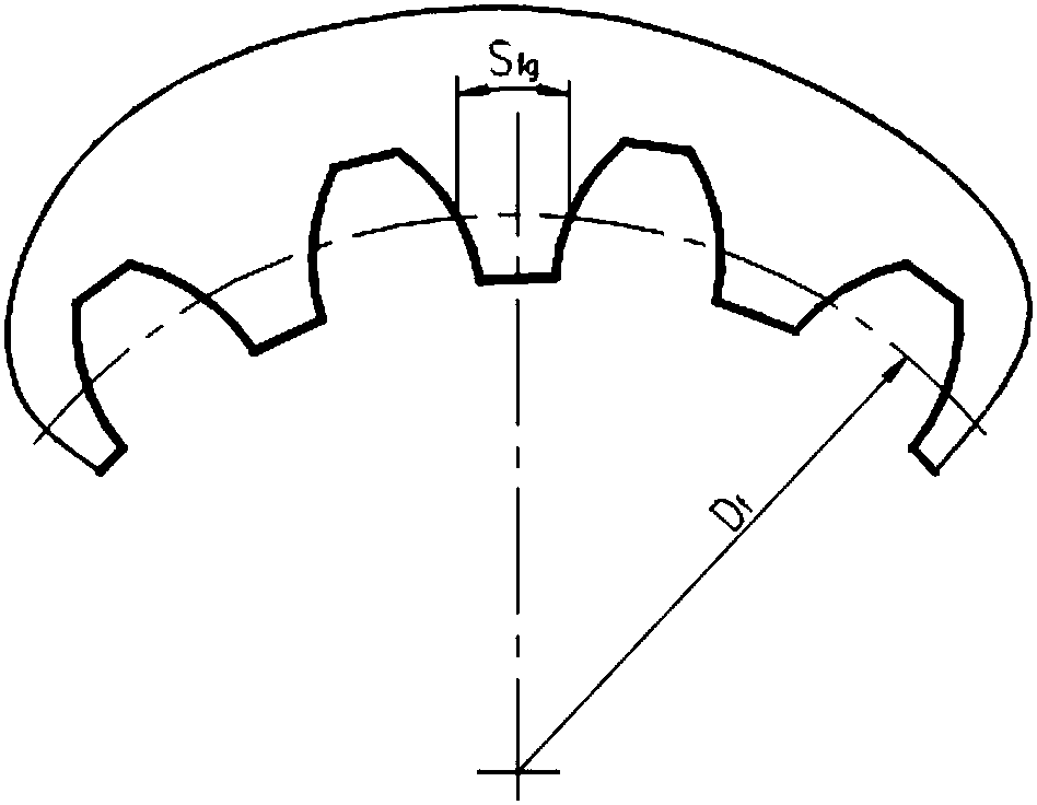
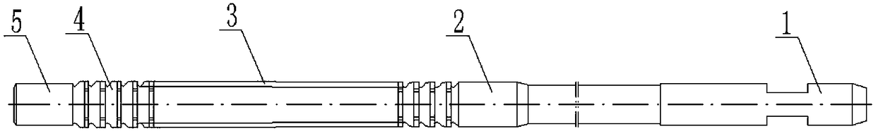
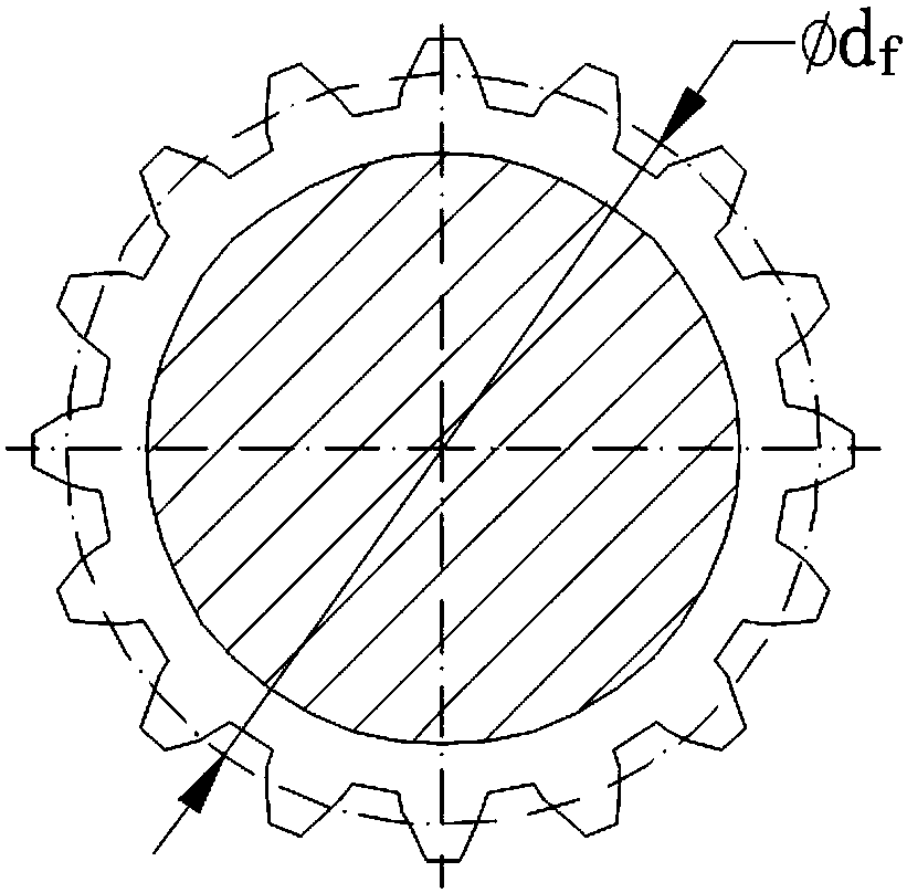
[0035] This embodiment provides a method for designing and manufacturing the teeth of an involute spline broach, the involute spline broach, such as figure 2 As shown, it includes a clamping part 1, a front guide part 2, a cutting tooth part 3, a correction tooth part 4 and a rear guiding part 5 along its axial direction. The correcting teeth of the correcting tooth section are distributed behind the cutting tooth section, and the correcting teeth have the same size and shape as the last cutting tooth, without taper. Therefore, as long as the cutter teeth of the cutting teeth are determined, the structure of the correcting teeth is also determined. Cutting teeth based on the Fig...


PUM


Abstract

The invention discloses a designing and manufacturing method for teeth of an involute spline broach. The designing and manufacturing method for the teeth of the involute spline broach comprises the steps that firstly, the tooth rise Sz of each tooth is determined according to parameters of a machined part; secondly, the lifting quantity coz of each tooth is determined according to the tooth rise Sz of the tooth; thirdly, an involute space curve of the teeth of the broach in the machining and grinding state is determined; and fourthly, a curve passing through the coordinate points of the involute space curve is drawn to serve as an involute space curve of the broach in the grinding state, and the teeth of the involute spline broach are obtained by conducting machining according to the involute space curve of the broach in the machining and grinding state. Since the designing and manufacturing method is based on the gradual cutting type broaching principle and machining is conducted on the basis that the involute space curve of the broach in the machining and grinding state is determined, the procedure of shoveling and grinding a rear corner during subsequent machining of a forming type broaching tool can be omitted, the broach machining process is simplified, the machining difficulty is lowered, and the producing and manufacturing cost is greatly reduced accordingly.

Description

technical field [0001] The invention belongs to the technical field of cutting tools, and relates to an involute spline broaching tool, in particular to a method for designing and manufacturing the teeth of an involute spline broach. Background technique [0002] Involute splines (such as figure 1 (shown) due to its large number of teeth, wide and thick tooth ends and roots, strong bearing capacity, easy self-centering, high installation accuracy, etc., the involute spline is widely used. However, the processing difficulty of involute spline is relatively high, and it is mainly prepared by broaching process through involute spline broach. Involute spline broach integrated structure, such as figure 2 As shown, it includes a clamping part 1, a front guide part 2, a cutting tooth part 3, a correction tooth part 4, and a rear guide part 5; at present, broaches for processing involute splines are mainly based on the principle of forming broaching, Make the comprehensive profi...

Claims


Application Information

Patent Timeline
Patent Type & Authority Patents(China)
IPC IPC(8): B23D43/02
CPCB23D43/02
Inventor 王红英张思尧
Owner AECC AERO SCI & TECH CO LTD
Why Eureka
Try Eureka