Oil wiping device

The technology of a driving device and a cylinder group is applied in cleaning methods and appliances, chemical instruments and methods, cleaning methods using tools, etc., and can solve problems such as complex structure of oil wiping equipment, unsatisfactory oil wiping effect, and complicated process settings. Achieve the effect of improving the competitiveness of the manufacturing industry, avoiding manual work, and high practicability

Active Publication Date: 2019-08-02
南通北外滩建设工程有限公司
View PDF10 Cites 0 Cited by
  • Summary
  • Abstract
  • Description
  • Claims
  • Application Information

AI Technical Summary

Problems solved by technology

[0006] The structure of the above-mentioned oil wiping equipment is too complicated, the process settings are complicated, the energy consumption is large, the consumption of raw materials is large, the oil wiping effect is not ideal, and maintenance is difficult, so it does not meet the requirements of today's society

Method used


Image

  • Oil wiping device
  • Oil wiping device
  • Oil wiping device

Examples


Embodiment Construction

[0030] Below in conjunction with accompanying drawing and specific embodiment the present invention is described in further detail:
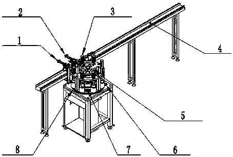
[0031] see figure 1

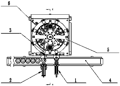
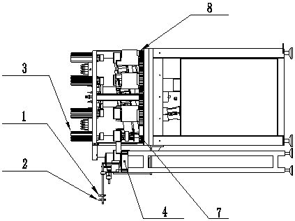
[0032] figure 1 It is a perspective view of the present invention. exist figure 1 Among them, the oil wiping device includes a conveyor belt group 4 connected to the driving device and a rotating bearing 5 provided with a pressing cylinder group 3 and a driving gear 6. The opposite side of the pressing cylinder group 3 is provided with a push cylinder group 2, and the push cylinder group 2 and the pressing cylinder group 3 are provided with a conveyor belt group 4, the push cylinder group 2 is provided with a suction cylinder group 1, and the driven gear 8 matching the driving gear 6 is provided below the rotating bearing 5, and the driven gear 8 Be provided with inclined paper tape 7 beside.

[0033] The pushing cylinder group 2 is connected with the pressing cylinder group 3 in transmission.

[0034] The pushing cyl...


PUM


Abstract

The invention discloses a novel oil applying device. The novel oil applying device comprises a conveyor belt group connected with a driving device in a transmission manner and a rotating bearing provided with a press cylinder group and a driving gear; a push cylinder group is arranged opposite to the press cylinder group; the conveyor belt group is arranged between the push cylinder group and the press cylinder group; a suction cylinder group is arranged behind the push cylinder group; a driven gear matched with the driving gear is arranged below the rotating bearing; an inclined paper tape is arranged beside the driven gear; the push cylinder group is connected with the push cylinder group in a transmission manner; the suction cylinder group and the push cylinder group are arranged on the same side of the conveyor belt group; the driving gear is connected with the driven gear in a transmission manner; and the driving gear and the driven gear are both connected with the paper tape in a transmission manner. The oil applying device disclosed by the invention has the advantages of complete automation of oil applying, good wiping effects, energy saving, environment protection, and high utilization rate of the paper tape, the working efficiency is improved, the resource utilization rate is increased, and the novel oil applying device has broad market economic benefits.

Description

technical field [0001] The invention relates to an oil rubbing machine, in particular to an oil rubbing device. Background technique [0002] At present, the cleaning of filter oil stains is basically done manually in the market. First of all, because it is manual operation, the efficiency is not very high, and it cannot reach the efficiency of machine operation at all; secondly, because it is manually wiped by hand, the utilization area of ​​oil-rubbing paper is small, accounting for about 30% of the whole paper, and Usually a piece of oil paper must be replaced after three or four times of wiping, and the utilization rate is relatively low, resulting in a certain amount of waste; comprehensively considered, the cost of manual operation is much higher than that of machines. [0003] Manual oiling has low work efficiency, high labor intensity, and high labor cost; manual oiling cannot maintain a uniform cleanliness, so the wiping effect is not ideal; when manual oiling is u...

Claims


Application Information

Patent Timeline
Patent Type & Authority Patents(China)
IPC IPC(8): B08B1/02
CPCB08B1/006B08B1/02
Inventor 方新国肖凯华寿庆
Owner 南通北外滩建设工程有限公司
Why Eureka
Try Eureka