CT coplanar puncture template provided with identifier guiding devices and making method of CT coplanar puncture template

A technology of a puncture template and a guiding device, which is applied in the field of medical equipment, can solve the problems of increased surgical risk, cumbersome use process, time-consuming, etc., and achieves the effects of reducing the number of CT scans, avoiding repeated puncture positioning, and alleviating the pain of patients.

Inactive Publication Date: 2017-05-10
蓝孝全 +1
View PDF0 Cites 5 Cited by
  • Summary
  • Abstract
  • Description
  • Claims
  • Application Information

AI Technical Summary

Problems solved by technology

The existing puncture template does not have a marking line that can be developed on CT, so the pinholes of the template cannot be quickly matched with the CT image, and the puncture needle needs to be inserted and verified repeatedly to determine the pinhole to be punctured, and multiple CT scans are required at the same time
Secondly, an additional fence-type locator needs to be installed during positioning, which is cumbersome and time-consuming to use
Thirdly, the existing template cannot predict the direction of the puncture needle, and it usually requires repeated puncture to position the puncture needle, which increases the pain of the patient and the number of CT scans, and increases the risk of surgery

Method used


Image

  • CT coplanar puncture template provided with identifier guiding devices and making method of CT coplanar puncture template
  • CT coplanar puncture template provided with identifier guiding devices and making method of CT coplanar puncture template
  • CT coplanar puncture template provided with identifier guiding devices and making method of CT coplanar puncture template

Examples


Embodiment 1

[0052] Follow the steps below to prepare a CT coplanar puncture template with an identification guide:

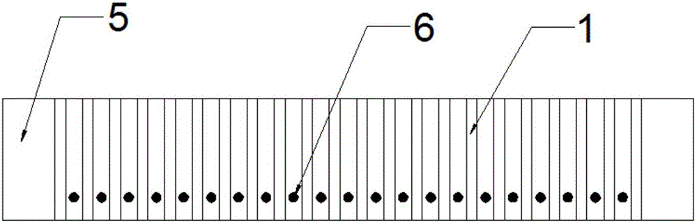
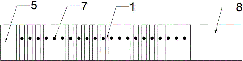
[0053] (1) 3D modeling: input the size information of the puncture template into the modeling software for 3D modeling. The size information includes the length of the plate body of 12 cm, width of 12 cm, and thickness of 1 cm, and the length of the fixed end of 12 cm, width of 2 cm, and thickness of 1 cm. The diameter of the puncture needle holes is 3mm, the spacing is 5mm, and the arrangement (rows and columns are neatly arranged), the position of the lead wire hole in the row (0.2cm from the upper surface), the hole diameter is 1.0mm, the position of the lead wire hole in the column (0.7cm from the upper surface), Aperture 1.0mm;

[0054] (2) Print out the puncture template with a single-hole 3D printer according to the 3D model of the established puncture template, and the printing material used is PLA;

[0055] (3) Insert a lead wire with a diameter of 0.5 mm into the...

Embodiment 2

[0061] Follow the steps below to prepare a CT coplanar puncture template with an identification guide:

[0062] (1) 3D modeling: input the size information of the puncture template into the modeling software for 3D modeling, the size information includes the length of the plate body 12cm, width 12cm, thickness 2cm, length of the fixed end 12cm, width 2cm, thickness 1.3cm , the diameter of the puncture needle holes is 1 mm, the spacing is 5 mm, and the arrangement (rows and columns are neatly arranged), the position of the lead wire holes in the rows (1.2 cm from the upper surface), the hole diameter is 1.6 mm, and the position of the lead wire holes in the columns (1.5 cm from the upper surface) , Aperture 1.6mm;

[0063] (2) Print out the puncture template with a single-hole 3D printer according to the 3D model of the established puncture template, and the printing material used is PLA;

[0064] (3) Insert a lead wire with a diameter of 1 mm into the lead wire hole, and seal...

Embodiment 3

[0069] Follow the steps below to prepare a CT coplanar puncture template with an identification guide:

[0070] (1) 3D modeling: input the size information of the puncture template into the modeling software for 3D modeling, the size information includes the length of the plate body 12cm, width 12cm, thickness 2cm, length of the fixed end 12cm, width 2cm, thickness 1.3cm , the diameter of the puncture pinholes is 1.87mm, the spacing is 5mm, and the arrangement (rows and columns are neatly arranged), the position of the row lead wire holes (0.9cm from the upper surface), the hole diameter is 1.6mm, and the position of the column lead wire holes (1.5cm from the upper surface ), aperture 1.6mm;

[0071] (2) Print out the puncture template with a single-hole 3D printer according to the 3D model of the established puncture template, and the printing material used is PLA;

[0072] (3) Insert a lead wire with a diameter of 1 mm into the lead wire hole, and seal the opening of the le...


PUM


Abstract

The invention relates to a CT coplanar puncture template provided with identifier guiding devices. The CT coplanar puncture template comprises a plate body, puncture needle holes, marking lines and lead wires, wherein the puncture needle holes are uniformly distributed in the plate body in rows and columns; the marking lines are arranged on the portions, positioned between any two rows of puncture needle holes and positioned between any two lines of puncture needle holes, of the surface of the plate body; the lead wires are embedded in portions, right below the marking lines, of the plate body; and the lead wires are consistent with the marking lines in length and are parallel with the marking lines. According to the coplanar puncture template provided with the identifier guiding devices, puncture directions of puncture needles can be precisely guided, the template can be placed in accordance with the position and size of a focus before an operation so as to avoid dangerous organs around the focus, the puncture needles can be precisely inserted, and by virtue of the template, the various puncture needles can be kept under a parallel state. The CT coplanar puncture template can shorten an operation time, reduce operation risks and reduce operation difficulty. The template is provided with the guiding lead wires as the puncture needle guiding devices, so that a doctor can intuitively predict moving trends of the puncture needles before inserting the puncture needles, and therefore CT scanning times and puncture difficulty are further reduced.

Description

technical field [0001] The invention belongs to the field of medical equipment, and in particular relates to a CT coplanar puncture template with an identification guide device. Background technique [0002] Tumor is a disease that seriously endangers human health and life. In recent years, the incidence rate has gradually increased, and the age of onset has gradually decreased. Early detection, correct diagnosis, and timely treatment have an important impact on prognosis. Whether it is pathological diagnosis or minimally invasive treatment (such as: radioactive seed implantation, radiofrequency, microwave ablation treatment), it is inseparable from extracorporeal puncture, and extracorporeal puncture is an important way to obtain pathological and minimally invasive treatments. [0003] The technique of freehand puncture is difficult and the learning period is long. Therefore, most doctors rely on puncture templates to achieve more precise positioning. Existing puncture te...

Claims


Application Information

Patent Timeline
Patent Type & Authority Applications(China)
IPC IPC(8): A61B17/34A61B6/03B33Y80/00B33Y70/00B33Y10/00
CPCA61B17/3403A61B6/032B33Y10/00B33Y70/00B33Y80/00
Inventor 蓝孝全田芳晓于江平马建林周大鹏
Owner 蓝孝全
Why Eureka
Try Eureka