Multifunctional small-size heating stove

A multi-functional, heating stove technology, which can be used in household stoves/stoves, stoves/stoves with hot water devices, and household heating, etc., and can solve the problems of leakage of soot, incomplete combustion, and poor combustion efficiency. , to achieve the effect of improving combustion efficiency, fully releasing heat, and increasing heat dissipation area

Inactive Publication Date: 2017-05-03
孙诚刚
View PDF0 Cites 0 Cited by
  • Summary
  • Abstract
  • Description
  • Claims
  • Application Information

AI Technical Summary

Problems solved by technology

Most of the small heating furnaces currently on the market are simple in structure and adopt the direct combustion method. The combustible gases such as carbon monoxide, methane, hydrogen, etc. generated in the combustion chamber are directly discharged from the flue with the heat flow, and the heat loss is large, and complete combustion cannot be achieved. Combustion efficiency Poor, the smoke outlet often emits black smoke, and the soot leaks out; every time coal is added, the coal window needs to be opened, and part of the heat is lost. In addition, coal must be added many times, which is troublesome; at the same time, once this kind of heating furnace encounters strong winds , it is especially easy to cause the phenomenon of falling smoke, and the environmental protection effect is poor

Method used


Image

  • Multifunctional small-size heating stove
  • Multifunctional small-size heating stove
  • Multifunctional small-size heating stove

Examples


Embodiment Construction

[0021] The present invention will be further described below in conjunction with the accompanying drawings and embodiments.

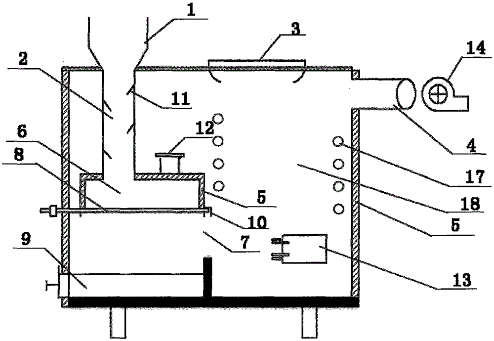
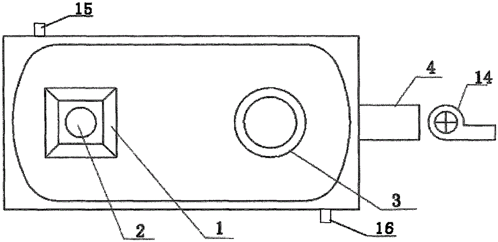
[0022] Such as figure 1 , 2 As shown, the present invention provides a kind of multifunctional small-sized heating furnace, comprises furnace body, coal storage box (1), cooking device (3) and smoke exhaust chimney (4); Furnace body internal cavity forms furnace (18), storage The coal box (1) and the cooking device (3) are located on the top of the furnace body. The coal storage box (1) is funnel-shaped, and its top is an open air inlet for adding coal; ), a row of grates (8) is arranged at the bottom of the anti-burning chamber (6), and an ash collection box (9) is installed directly below the fire grate, and a lower smoke outlet (7) is arranged between the fire grate and the ash collection box, A lower coal pipe (2) is installed between the anti-burning chamber (6) and the coal storage box (1), and the anti-burning chamber (6), the coal storage box ...


PUM


Abstract

The invention provides a multifunctional small-size heating stove. The multifunctional small-size heating stove comprises a stove body, a coal storing box, a cooking device and a smoke exhausting barrel, wherein an empty chamber in the stove body forms a hearth; the coal storing box and the cooking device are positioned on the top part of the stove body; the coal storing box is funnel-shaped, and an opened coal feeding and air inlet port is formed in the top end of the coal storing box; a re-burning chamber is arranged in the stove body, and a row of grates is arranged at the bottom part of the re-burning chamber; an ash collecting box is mounted under the grates; a lower smoke exhausting port is formed between the grates and the ash collecting box; a coal feeding pipe is mounted between the re-burning chamber and the coal storing box; an obliquely-downward baffle plate is arranged in the coal feeding pipe; the re-burning chamber, the coal storing box and the coal feeding pipe are in the same vertical direction and positioned at the front side of the stove body; the smoke exhausting barrel is arranged at the upper part of the rear side of the stove body; an air drafting device, which is an air exhaust fan or a centrifugal induced draft fan, is arranged inside or outside the smoke exhausting barrel; the grates can be intercommunicated water pipe fire bars which are arranged in a row; a water sleeve is arranged in the periphery of the re-burning chamber and positioned at the inner side of the stove body; a spirally-coiled heat absorbing water pipe is arranged in the hearth; a baking chamber is arranged at one side of the stove body.

Description

technical field [0001] The invention relates to a civil stove, in particular to a multifunctional small heating stove. Background technique [0002] Along with raising day by day of people's living standard, the use of small-sized civil heating stove has become more and more popular, especially in vast rural area, the stove of heating and cooking is more popular. Most of the small heating furnaces currently on the market are simple in structure and adopt the direct combustion method. The combustible gases such as carbon monoxide, methane, hydrogen, etc. generated in the combustion chamber are directly discharged from the flue with the heat flow, and the heat loss is large, and complete combustion cannot be achieved. Combustion efficiency Poor, the smoke outlet often emits black smoke, and the soot leaks out; every time coal is added, the coal window needs to be opened, and part of the heat is lost. In addition, coal must be added many times, which is troublesome; at the same...

Claims


Application Information

Patent Timeline
IPC IPC(8): F24B1/183F24B1/191
Inventor 孙诚刚
Owner 孙诚刚
Why Eureka
Try Eureka