
Double-sealing structure of microwave resonant cavity

A technology of microwave resonant cavity and cavity door, which is applied in microwave heating and other directions, and can solve the problems of gas sealing and microwave shielding

Active Publication Date: 2017-04-26
RES INST OF PHYSICAL & CHEM ENG OF NUCLEAR IND
View PDF2 Cites 0 Cited by
  • Summary
  • Abstract
  • Description
  • Claims
  • Application Information

AI Technical Summary

Problems solved by technology

[0004] Anti-microwave leakage mainly adopts measures such as choke device, assembly of ferrite and other absorbing strips, hole array metal plate, and cut-off waveguide. Although these methods can prevent microwave leakage, they cannot make the gas airtight
Gas-tight methods such as plastic sealing strips and gaskets commonly used cannot shield microwaves.

Method used


Image

  • Double-sealing structure of microwave resonant cavity
  • Double-sealing structure of microwave resonant cavity

Examples


Embodiment Construction

[0022] The double-sealed structure of the microwave resonator of the present invention will be described in detail below in conjunction with the drawings and embodiments of the description:

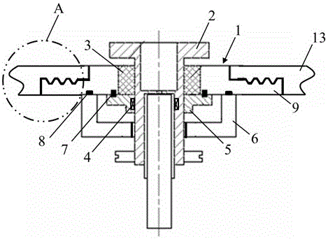
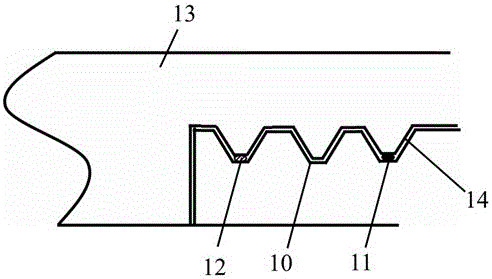
[0023] Such as figure 1 , 2 As shown, a double-sealed structure of a microwave resonator includes a cavity door 1 with a convex longitudinal section and a central hole. The rotating shaft 2 is dynamically sealed and fixed on the cavity door 1 through a fluorine rubber oil seal ring 3 arranged outside it. In the center hole, the self-aligning bearing 4 is arranged on the outside of the rotating shaft 2, and the self-aligning bearing 4 is installed in the horizontal bearing seat 5, and the horizontal bearing seat 5 is fixed to the lower end surface of the chamber door 1, and the contact surface of the two is provided with a first-grade graphite The sealing ring 7; the outer cover of the horizontal bearing seat 5 is provided with a bearing seat cover 6, and the bearing seat cover 6 is fixed...


PUM


Abstract

The present invention discloses a double-sealing structure of a microwave resonant cavity. The structure comprises a cavity door, a rotation shaft is dynamically sealed in the central hole of the cavity door through a fluorelastomer oil seal ring arranged at the external portion of the rotation shaft, the external portion of the rotation shaft is provided with a self-aligning bearing which is installed in a horizontal bearing pedestal, the horizontal bearing pedestal is fixed with the lower end surface of the cavity door, and the contact surface therebetween is provided with a first-level carbon seal ring; the external portion of the horizontal bearing pedestal is provided coated with a bearing pedestal cover which is fixed with the lower end surface of the cavity door, and the contact surface therebetween is provided with a second-level carbon seal ring; dovetail grooves matching with a boss on the external cavity wall of the resonant cavity are arranged at the upper end surface of the shoulder of the cavity door; and a carbon seal ring is arranged between the innermost dovetail groove and the boss, and a fluororubber O-shaped ring is arranged between the outermost dovetail groove and the boss. Air is compressed into the resonant cavity to 30 kPa and then the air compression is stopped, and the voltage in the cavity has no change after 30mins. When the microwave power is equal to 1 kW, the measurement is performed at the position having a distance of 20cm from the cavity door, and the microwave leakage rate is smaller than 0.1mW / cm2.

Description

technical field [0001] The invention belongs to a structure used for sealing a door gap of a microwave resonant cavity and a rotating transmission part, and in particular relates to a double-closed structure of a microwave resonant cavity. Background technique [0002] Microwaves rely on high-frequency electromagnetic wave oscillations to induce the movement of charged particles, generate dielectric loss, and heat the material as a whole. It has the characteristics of fast heating speed, uniformity, selectivity, high energy utilization rate, and no lag. With the application of microwave in hydrometallurgy, food drying, organic synthesis, sample processing, material sintering, waste treatment, etc., microwave equipment has also been developed and promoted. [0003] However, microwave radiation is very harmful to the human body. Together with air pollution, water pollution and noise pollution, it has become the four major public hazards of environmental pollution. It is necess...

Claims


Application Information

Patent Timeline
IPC IPC(8): H05B6/76
CPCH05B6/76
Inventor 赵刚于震孙亮伍华彬
Owner RES INST OF PHYSICAL & CHEM ENG OF NUCLEAR IND
Learn More