
Air inlet mechanism and reaction cavity

A technology of air intake mechanism and chamber cover, applied in the direction of electrical components, discharge tubes, circuits, etc., can solve the problems of nozzle seal failure and looseness, and achieve the effect of ensuring position fixation and sealing

Active Publication Date: 2017-04-26
BEIJING NAURA MICROELECTRONICS EQUIP CO LTD
View PDF8 Cites 11 Cited by
  • Summary
  • Abstract
  • Description
  • Claims
  • Application Information

AI Technical Summary

Problems solved by technology

[0006] The present invention aims to solve at least one of the technical problems existing in the prior art, and proposes an air intake mechanism and a reaction chamber, which can avoid problems such as sealing failure and loosening of the nozzle relative to the reaction chamber in a high-temperature environment

Method used


Image

  • Air inlet mechanism and reaction cavity
  • Air inlet mechanism and reaction cavity

Examples


Embodiment Construction

[0022] In order to enable those skilled in the art to better understand the technical solution of the present invention, the intake mechanism and the reaction chamber provided by the present invention will be described in detail below with reference to the accompanying drawings.

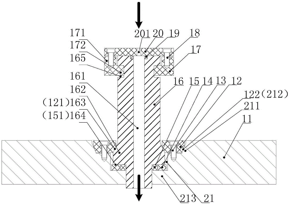
[0023] figure 2 It is a sectional view of the intake mechanism provided by the embodiment of the present invention. Such as figure 2 As shown, the gas inlet mechanism is used to deliver gas from the top of the reaction chamber to the reaction chamber. The intake mechanism includes a nozzle 16, a wedge 12, an upper sealing assembly and a lower sealing assembly. Wherein, the nozzle 16 is installed in the installation hole 21 of the chamber cover plate 11, and the lower end of the nozzle 16 passes through the installation hole 21, so that the gas outlet end of the gas path 161 communicates with the interior of the reaction chamber. Moreover, a first wedge-shaped portion 162 is provided around the l...


PUM


Abstract

The invention provides an air inlet mechanism and a reaction cavity. The air inlet mechanism comprises a nozzle, a wedge-shaped piece, an upper sealing assembly and a lower sealing assembly. The nozzle is installed in an installation hole of a cover plate of the cavity, the lower portion of the outer circumferential wall of the nozzle is provided with a first wedge-shaped part in an encircling manner, and a second wedge-shaped part is formed in the position, close to the upper surface of the cover plate of the cavity, of the installation hole. The wedge-shaped piece cooperates with the first and second wedge-shaped parts to fix the nozzle in the installation hole and generate a horizontal and downward stress during thermal deformation. The upper sealing assembly seals an opening in the top end of the nozzle. The lower sealing assembly seals a gap between the nozzle and the cover plate of the cavity. The air inlet mechanism provided by the invention can be used to solve the problems that the nozzle is in sealing failure or is loosened relative to the reaction cavity in the high-temperature environment.

Description

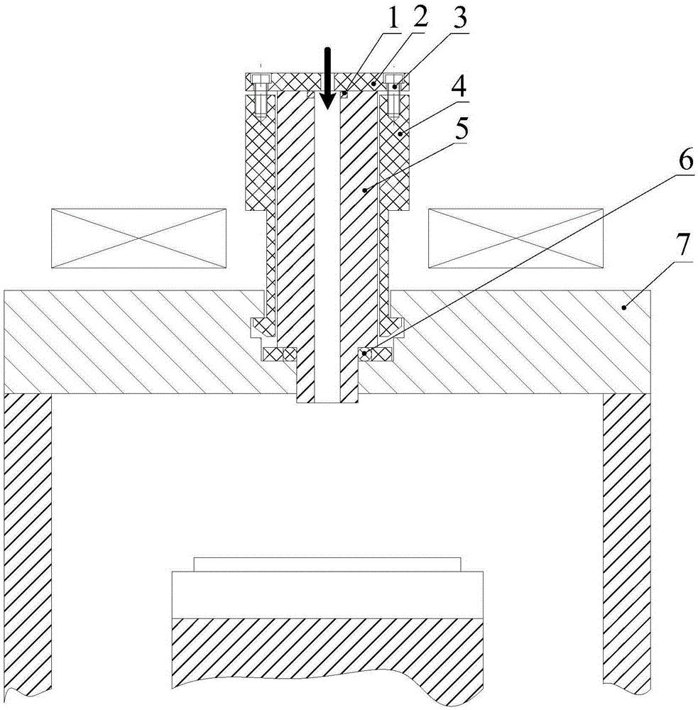
technical field [0001] The invention relates to the field of semiconductor manufacturing, in particular to an air intake mechanism and a reaction chamber. Background technique [0002] In processes such as plasma etching (ETCH), physical vapor deposition (PVD), chemical vapor deposition (CVD), etc., it is usually necessary to provide an air inlet mechanism for delivering process gas into the reaction chamber. [0003] figure 1 It is a sectional view of an existing air intake mechanism. Such as figure 1 As shown, the intake mechanism includes a nozzle 5 , a fixing part 4 and a pressing part 2 . Wherein, the nozzle 5 is made of ceramic material, which is installed on the chamber cover plate 7, and is used for delivering the process gas into the reaction chamber. Moreover, a sealing ring 6 is provided between the nozzle 5 and the chamber cover plate 7 to seal the gap between them. The fixing part 4 is made of resin material, which is sheathed on the outside of the nozzle 5...

Claims


Application Information

Patent Timeline
Patent Type & Authority Applications(China)
IPC IPC(8): H01J37/32
CPCH01J37/3244H01J37/32513
Inventor 赵隆超
Owner BEIJING NAURA MICROELECTRONICS EQUIP CO LTD
Learn More