Back light module
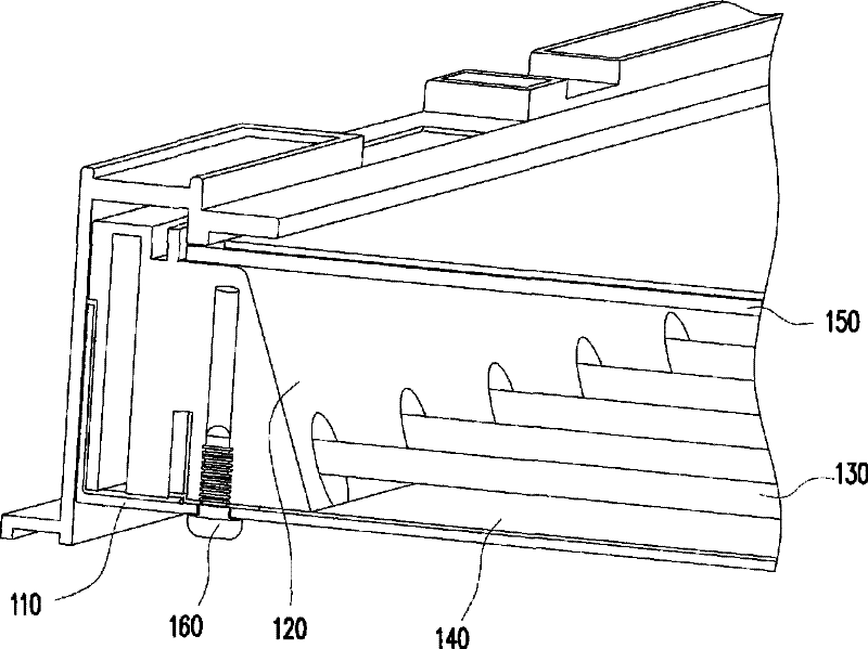
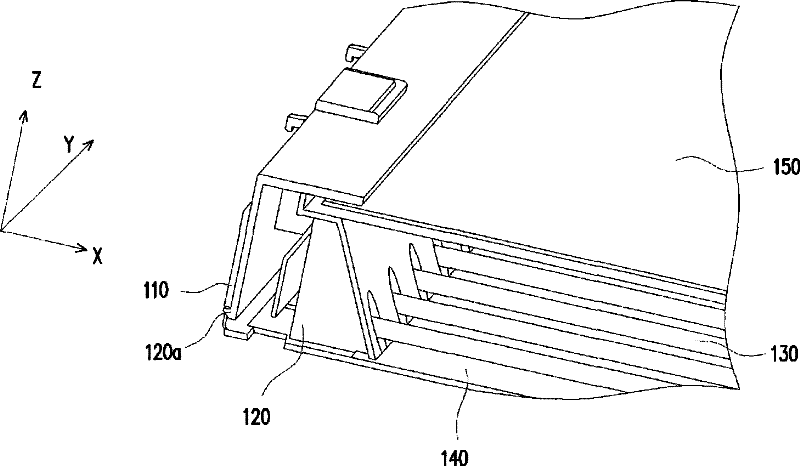
A technology for a backlight module and a backplane, which is applied in the field of backlight modules in which the frame structure has a claw structure and/or an adhesive layer, can solve the problem that the claw structure 120a is not easy to form, the design number of the claw is difficult to estimate, and the assembly is difficult or bad. and other problems, to achieve the effect of reducing assembly difficulty and assembly time, improving production yield, and reducing time and price
- Summary
- Abstract
- Description
- Claims
- Application Information
AI Technical Summary
Problems solved by technology
Method used
Image

Examples
no. 1 example
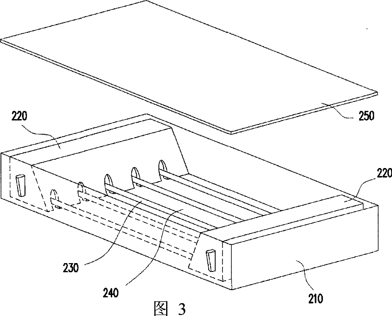
[0059] FIG. 3 is a schematic diagram of a backlight module according to an embodiment of the present invention. Figure 4A It is a partial schematic diagram of the side frame of the back panel of the first embodiment of the present invention. Please refer to Figure 3 with Figure 4A , in this embodiment, the backplane side frame 220 has a bottom surface 222 , a front surface 224 , a rear surface 226 , an upper surface 228 and two second side surfaces 229 . The front surface 224 has a plurality of lamp tube fixing portions 224a, and each second side surface 229 has at least one claw structure 229a. Compared to figure 2 According to the known method, in this embodiment, the claw structure 229a is designed on the second side surface 229 of the side frame 220 of the back panel, so that the claw structure 229a can be injection molded together with the side frame 220 of the back panel more simply to form an integral body Molded structure, and its material can be plastic or metal...
no. 2 example
[0065] FIG. 3 is a schematic diagram of a backlight module according to an embodiment of the present invention. Figure 5A It is a partial schematic diagram of the backlight module and the adhesive layer according to the second embodiment of the present invention. Please refer to Figure 3 with Figure 5A , the backlight module includes a backplane main body 210 , two backplane side frames 220 , a plurality of lamp tubes 230 , a reflection sheet 240 , a diffusion plate 250 and an adhesive layer 260 . The backboard main body 210 has a bottom surface 212 and at least two first side surfaces 214 . The two backplane side frames 220 are respectively disposed on the two opposite first side surfaces 214 of the backplane main body 210, wherein each backplane side frame 220 has a bottom surface 222, a front surface 224, a rear surface 226, a The upper surface 228 and two second side surfaces 229 .
[0066] please refer again Figure 5A The front surface 224 of the backboard side fra...
no. 3 example
[0074] Figure 7A It is a partial schematic diagram of the backlight module of the third embodiment of the present invention. Please refer to Figure 7A , this embodiment is a combination of the first embodiment and the second embodiment. In this embodiment, it is characterized in that the claw structure 229a on the second side surface 229 of the backboard side frame 220 and the claw structure 229a arranged on the backboard side frame 220 The adhesive layer 260 between the bottom surface 222 of the backplane main body 210 and the bottom surface 212 of the backplane main body 210 uses the claw structure 229a to enable the backplane main body 210 and the backplane side frame 220 to be combined by directly pressing down and snapping together, and The bottom surface 222 of the side frame 220 of the backplane and the bottom surface 212 of the main body 210 of the backplane are fixed by a more simple pasting method, so the assembly of the backlight module is more convenient and relia...
PUM
 Abstract
Description
Claims
Application Information
 - R&D
- Intellectual Property
- Life Sciences
- Materials
- Tech Scout
- Unparalleled Data Quality
- Higher Quality Content
- 60% Fewer Hallucinations
Browse by: Latest US Patents, China's latest patents, Technical Efficacy Thesaurus, Application Domain, Technology Topic, Popular Technical Reports.
© 2025 PatSnap. All rights reserved.Legal|Privacy policy|Modern Slavery Act Transparency Statement|Sitemap|About US| Contact US: help@patsnap.com