Electronic cam control system and control method
An electronic cam and control system technology, applied in the general control system, control/adjustment system, electrical program control, etc., can solve the problems of troublesome maintenance and replacement, large mechanical cam wear, etc., achieve simple and convenient maintenance and avoid precision errors , reliable effect
- Summary
- Abstract
- Description
- Claims
- Application Information
AI Technical Summary
Problems solved by technology
Method used
Image

Examples
Embodiment 1
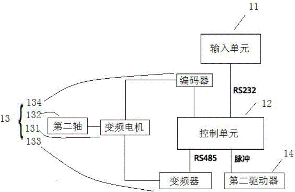
[0034] figure 1 It is a schematic diagram of the structure of the electronic cam control system of the present invention, such as figure 1 As shown, this embodiment provides an electronic cam control system, the electronic cam control system is used in a filling line, the filling line includes a conveyor belt and a filling station, the conveyor belt carries the packaging to be filled, the After the moving speed of the filling station is synchronized with the moving speed of the conveyor belt, the filling station fills the package to be filled with liquid. The electronic cam control system includes an input unit 11, a control unit 12, and a first driver 13 and the second driver 14, wherein: the input unit 11 sends the control parameter to the control unit 12; the control unit 12 controls the movement of the first driver 13 according to the control parameter, and the control unit 12 controls the movement of the first driver 13 according to the The movement of the second driver ...
Embodiment 2
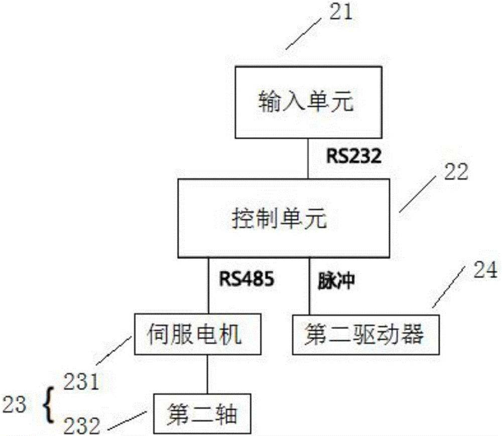
[0039] figure 2 It is a schematic diagram of the structure of the electronic cam control system of the present invention, such as figure 2As shown, in the electronic cam control system provided in this embodiment, the electronic cam control system includes an input unit 21, a control unit 22, a first driver 23 and a second driver 24. The difference from the previous embodiment is that the The first driver 23 includes a first motor and a first shaft 232, wherein: the first motor is a servo motor 231; through the virtual main shaft function of the servo motor 231, no encoder needs to be installed, so that the second shaft is opposite to the first shaft The position is absolutely synchronized, thereby avoiding the accuracy error caused by the encoder. Regardless of high speed, low speed, acceleration and deceleration, the first axis and the second axis run reliably synchronously, and all control axes are linked to ensure absolute synchronization of control commands, avoiding c...
Embodiment 3
[0043] The present invention also provides an electronic cam control method, the electronic cam control method comprising:
[0044] Inputting control parameters to the control unit through the input unit;
[0045] The control unit calculates the motion parameters of the first driver according to the control parameters, and calculates the motion parameters of the second driver through the motion parameters of the first driver;
[0046] The first driver performs linear motion for driving the conveyor belt;
[0047] The second driver makes a linear motion and is used to drive the filling station.
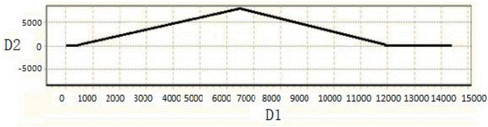
[0048] Combined with the above electrical structure and electronic cam tracking curve, the specific control process is as follows:
[0049] First, calculate the electronic cam curve and the speed multiplier of the master and slave axes according to the mechanical parameters, encoder resolution and the number of filled bottles to ensure that the speed of the master and slave axes is t...
PUM
 Abstract
Description
Claims
Application Information
 - R&D
- Intellectual Property
- Life Sciences
- Materials
- Tech Scout
- Unparalleled Data Quality
- Higher Quality Content
- 60% Fewer Hallucinations
Browse by: Latest US Patents, China's latest patents, Technical Efficacy Thesaurus, Application Domain, Technology Topic, Popular Technical Reports.
© 2025 PatSnap. All rights reserved.Legal|Privacy policy|Modern Slavery Act Transparency Statement|Sitemap|About US| Contact US: help@patsnap.com