
Method and device of signal connection of mainboard and small board

A technology for connecting motherboards and signals, applied in the directions of connection, coupling device, measuring device, etc., can solve the problems of high cost, large wiring area of ​​the motherboard, and large insertion loss of radio frequency signals.

Active Publication Date: 2017-04-26
湖州帷幄知识产权运营有限公司
View PDF7 Cites 6 Cited by
  • Summary
  • Abstract
  • Description
  • Claims
  • Application Information

AI Technical Summary

Problems solved by technology

The multi-functional radio frequency test socket improves the space utilization rate of the circuit board. The above-mentioned existing patented technology has the above deficiencies, such as occupying a large wiring area of ​​the main board, high cost, and large radio frequency signal insertion loss.

Method used


Image

  • Method and device of signal connection of mainboard and small board
  • Method and device of signal connection of mainboard and small board

Examples


Embodiment 1

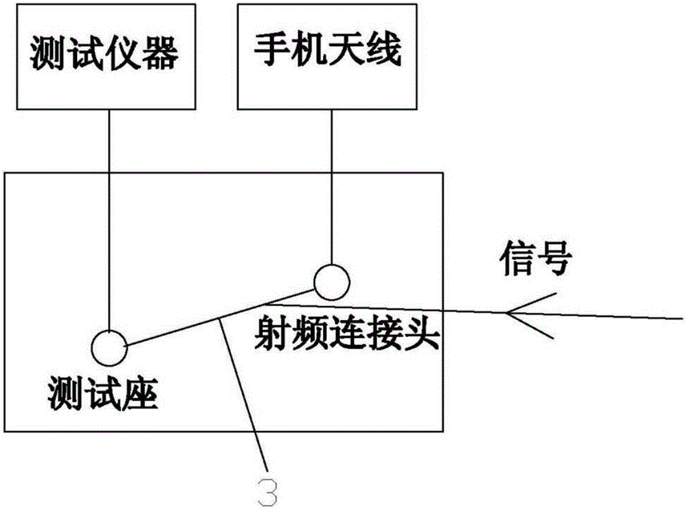
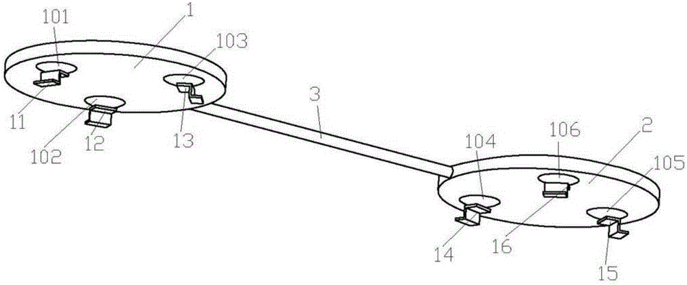
[0033] In this embodiment, a device for connecting signals of a main board and a small board includes a radio frequency testing device, a main board and a small board arranged on the radio frequency testing device;

[0034] A test socket is installed on the main board, and a radio frequency connector is installed on the small board;

[0035] The test socket is used for calibrating and testing the indicators of radio frequency signals;

[0036] The radio frequency connector is used to connect the radio frequency signal to the mobile phone antenna;

[0037] A radio frequency connection line 3 is used to connect the test socket and the radio frequency connector.

[0038] The radio frequency test device adopts one radio frequency test device, and the test socket and the radio frequency connector are packaged in a radio frequency test device at the same time. Through the connection of the radio frequency connecting line 3, the transmitted radio frequency signal can reach the test ...

Embodiment 2

[0076] This embodiment is a method for connecting the signals of the main board and the small board, including the following steps,

[0077] Step 1, packaging the test socket and the radio frequency connector in a radio frequency test device;

[0078] Step 2, use a radio frequency connecting line 3 to connect the test socket and the radio frequency connector;

[0079] Step 3, the radio frequency module outputs a radio frequency signal, and the radio frequency signal reaches the radio frequency connection line 3 between the test socket and the radio frequency connector of the radio frequency test device after passing through the radio frequency switch.

[0080] The test socket is used for calibrating and testing the indicators of radio frequency signals;

[0081] The radio frequency connector is used to connect the radio frequency signal to the mobile phone antenna;

[0082] The test socket is installed on the main board, and the radio frequency connector is installed on the ...


PUM


Abstract

The present invention relates to the radio frequency test technology field, especially to a method and a device of signal connection of a mainboard and a small board. The device comprises a radio frequency test device, and a mainboard and a small board arranged on the radio frequency test device. The main board is provided with a test bench, and the small board is provided with a radio frequency connection head; the test bench is configured to calibrate and test the indexes of radio-frequency signals; the radio frequency connection head is configured to connect the radio-frequency signals to a mobile phone antenna; and a radio-frequency connecting line is connected between the test bench and the radio frequency connection head. The method and device of signal connection of the mainboard and the small board are firm and stable in structure, small in occupied wiring area of the mainboard, low in cost and small in the radio-frequency signal insertion loss, etc.

Description

technical field [0001] The invention relates to the technical field of radio frequency testing, in particular to a method and a device for connecting signals of a main board and a small board. Background technique [0002] For the mobile phone with broken board design, the current design plan: 1. The signal enters the test socket. Under normal circumstances, the internal shrapnel of the test socket is connected to the left pin, and the signal enters the RF connector; 2. When the workshop is performing calibration tests, The shrapnel inside the test seat is lifted, and the signal enters the test instrument from the test line; 3. Under normal circumstances, when the calibration test is not in the workshop, the signal enters the RF connector, and then connects to the antenna with an RF cable. The current design will occupy the wiring area of ​​the motherboard, increase the cost, and increase the insertion loss of the radio frequency signal at the same time. [0003] For exampl...

Claims


Application Information

Patent Timeline
IPC IPC(8): G01R1/04H01R13/02H01R31/06
CPCG01R1/0416H01R13/02H01R31/06H01R2201/20
Inventor 薛正云
Owner 湖州帷幄知识产权运营有限公司
Learn More