
Laser particle size analyzer

A technology of laser particle size analyzer and laser light source, which is applied in the field of laser particle size analyzer, can solve the problems of decreased pixel utilization rate of CCD detector and reduction of photosensitive surface, etc., and achieves high pixel point utilization rate and increased photosensitive area effect

Inactive Publication Date: 2017-04-26
CHANGCHUN INST OF OPTICS FINE MECHANICS & PHYSICS CHINESE ACAD OF SCI
View PDF6 Cites 6 Cited by
  • Summary
  • Abstract
  • Description
  • Claims
  • Application Information

AI Technical Summary

Problems solved by technology

This reduces the pixel utilization of the CCD detector and reduces the photosensitive surface used for laser particle size analyzer detection.

Method used


Image

  • Laser particle size analyzer
  • Laser particle size analyzer
  • Laser particle size analyzer

Examples


Embodiment Construction

[0025] In order to make the purpose, technical solutions and advantages of the embodiments of the present invention clearer, the technical solutions in the embodiments of the present invention will be clearly and completely described below in conjunction with the drawings in the embodiments of the present invention. Obviously, the described embodiments It is a part of embodiments of the present invention, but not all embodiments. Based on the embodiments of the present invention, all other embodiments obtained by persons of ordinary skill in the art without making creative efforts belong to the protection scope of the present invention.

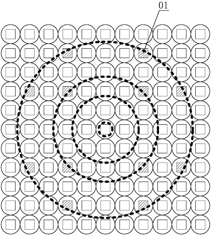
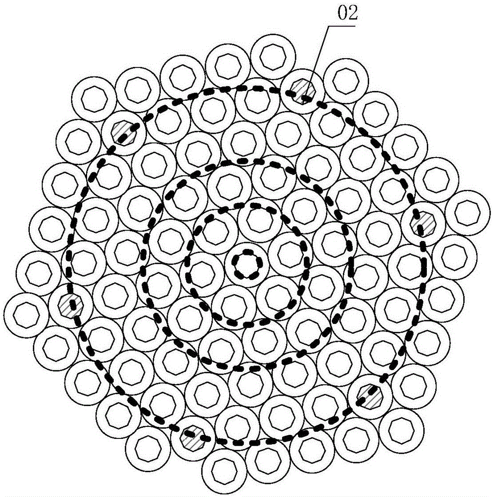
[0026] Please refer to figure 1 with 3 , figure 1 Schematic diagram of the structure of the laser particle size analyzer provided by the embodiment of the present invention; image 3 It is a schematic diagram of a concentric circular array photodetector provided by an embodiment of the present invention.

[0027] In a specific embodiment,...


PUM

PropertyMeasurementUnit
radiusaaaaaaaaaa

Abstract

The invention discloses a laser particle size analyzer. The laser particle size analyzer comprises a laser light source for emitting a laser beam, a sample placement device for holding a sample to be measured, a photodetector which is used for receiving scattered lights produced by the laser beam passing through the sample to be measured and transforming the scattered lights into a scattered light energy distribution graph and is a concentric array photodetector composed of a plurality of polygonal light emitting diodes, and a calculator for calculating particle size distribution of the sample to be measured according to the scattered light energy distribution graph. Based on the concentric array photodetector composed of a plurality of polygonal light emitting diodes, pixels simultaneously in two adjacent rings are fewer so that a pixel use ratio is high and a laser particle size analyzer detection photosensitive area is increased.

Description

technical field [0001] The invention relates to the technical field of instruments and meters, in particular to a laser particle size analyzer. Background technique [0002] The laser particle size analyzer is an instrument for testing the particle size distribution and particle size based on the particle's ability to diffract or scatter laser light to obtain a scattering spectrum. Its specific working principle is as follows: Since the laser has good monochromaticity and strong directionality, a beam of parallel laser light will irradiate to an infinite distance in an infinite space without hindrance, and it will be very fast during the propagation process. There is little divergence; when the beam is blocked by particles, part of the light will be scattered, and the propagation direction of the scattered light will form an angle θ with the propagation direction of the main beam. Scattering theory and experimental results tell us that the size of the scattering angle θ is ...

Claims


Application Information

Patent Timeline
Patent Type & Authority Applications(China)
IPC IPC(8): G01N15/02
CPCG01N15/0211
Inventor 党博石刘英隋龙
Owner CHANGCHUN INST OF OPTICS FINE MECHANICS & PHYSICS CHINESE ACAD OF SCI
Learn More