Optical fiber type three-dimensional trigger probe device and measuring method

A measurement method and optical fiber technology, applied in measurement devices, optical devices, instruments, etc., can solve the problems of limited structure, false triggering, and restricting measurement accuracy, and achieve strong applicability, adjustable trigger accuracy, and solve measurement errors. Effect

Active Publication Date: 2017-04-26
SHENZHEN GRADUATE SCHOOL TSINGHUA UNIV
View PDF4 Cites 9 Cited by
  • Summary
  • Abstract
  • Description
  • Claims
  • Application Information

AI Technical Summary

Problems solved by technology

No matter which method of sensing trigger is used, the contact of the measuring end drives the measuring rod to shift and trigger together. The existing anisotropy and the deformation of the measuring rod caused by contacting the measuring part will bring errors, although it can be Change the measurement sensing method and reduce the touch force to reduce the error, but not eliminate it essentially, which will lead to factors such as false triggering and affect the wide use of the probe
[0005] To sum up, the contact trigger probe is currently the most widely used, but its structure is limited, which restricts the improvement of its measurement accuracy. Therefore, it is necessary to fundamentally eliminate the anisotropy and the force and deformation of the measuring rod. Error, it is necessary to break through the traditional trigger measurement model, so that the accuracy of the contact trigger probe can be further improved

Method used


Image

  • Optical fiber type three-dimensional trigger probe device and measuring method
  • Optical fiber type three-dimensional trigger probe device and measuring method
  • Optical fiber type three-dimensional trigger probe device and measuring method

Examples


Embodiment Construction

[0033] Embodiments of the present invention will be described in detail below. It should be emphasized that the following description is only exemplary and not intended to limit the scope of the invention and its application.

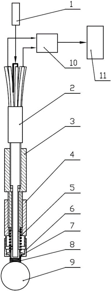
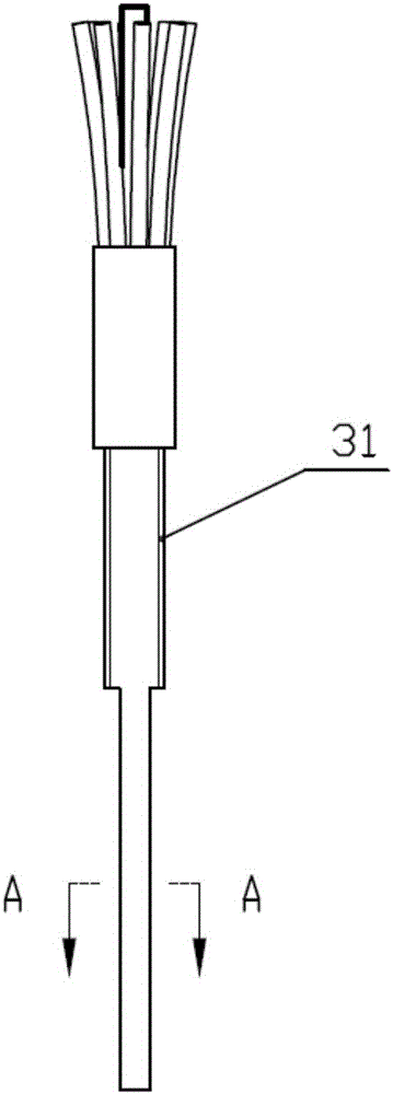
[0034] refer to Figure 1 to Figure 5 , in one embodiment, a fiber-optic three-dimensional trigger probe device, including a light source 1, an optical fiber measuring rod 2, an elastic reset mechanism, a measuring ball 9 coated with a reflective film, and a photoelectric detection unit, the optical fiber measuring rod 2 There is a central optical fiber 41 and 4N receiving optical fibers 42 uniformly distributed coaxially around the central optical fiber, N is a positive integer, and the elastic reset mechanism is arranged between the optical fiber measuring rod 2 and the measuring ball 9 In order to reset the measuring ball 9 to its initial position, the light source 1 emits light with constant power and transmits it to the measuring ball 9 through th...


PUM


Abstract

The invention discloses an optical fiber type three-dimensional trigger probe device and measuring method. The device comprises a light source, a fiber measuring rod, an elastic resetting mechanism, a measuring ball plated with a reflection film and a photoelectric detection unit. The fiber measuring rod is provided with a central fiber and 4N receiving fibers uniformly distributed around the central fiber in a coaxial manner wherein N is a positive integer; the elastic resetting mechanism is arranged between the fiber measuring rod and the measuring ball to make the measuring ball reset to its original position. The light with constant power generated from the light source is transmitted to the measuring ball through the central fiber and the light reflected by the reflection film is transmitted to the photoelectric detection unit through the receiving fibers. The device of the invention is capable of overcoming the measurement errors brought about by the deformation of the measuring rod in the probing and at the same time, has a relatively high resolution and achieves precise measurement.

Description

technical field [0001] The invention relates to the field of optical precision measurement, in particular to an optical fiber type three-dimensional trigger measuring head device and a measurement method. Background technique [0002] In recent years, with the rapid development of the automobile industry, electronics industry, aerospace industry and national defense industry, higher and higher requirements have been put forward for technical fields such as micro-machines, ultra-precision machining, and micro-assembly, making the parts of each part The requirements are getting higher and higher, the precision requirements for the processed precision parts are becoming more and more stringent, and the requirements for the instruments for testing these precision parts are also getting higher and higher. For testing and measuring instruments, a three-coordinate measuring machine (CMM) is a typical precision measuring instrument. [0003] Since the advent of the first quasi-coor...

Claims


Application Information

Patent Timeline
Patent Type & Authority Applications(China)
IPC IPC(8): G01B11/00
CPCG01B11/007
Inventor 刘厚德梁斌武万多陈艳华王学谦
Owner SHENZHEN GRADUATE SCHOOL TSINGHUA UNIV
Why Eureka
Try Eureka