Water-saving fog-dissipation closed cooling tower with float valve structure

A closed-type cooling tower and demisting closed-type technology, applied in the direction of water shower coolers, direct contact heat exchangers, fixed conduit components, etc., can solve the problems of spray water evaporation loss and reduce evaporation loss and wind blowing loss, easy installation and maintenance, and the effect of reducing outlet air temperature and humidity

Inactive Publication Date: 2017-04-26
SUN YAT SEN UNIV
View PDF10 Cites 0 Cited by
  • Summary
  • Abstract
  • Description
  • Claims
  • Application Information

AI Technical Summary

Problems solved by technology

[0004] In order to solve the spray water evaporation loss and a series of problems caused by the closed cooling tower equipment in the prior art, the present invention provides a water-saving and fog-eliminating closed cooling tower with a floating valve structure

Method used


Image

  • Water-saving fog-dissipation closed cooling tower with float valve structure
  • Water-saving fog-dissipation closed cooling tower with float valve structure

Examples


Embodiment 1

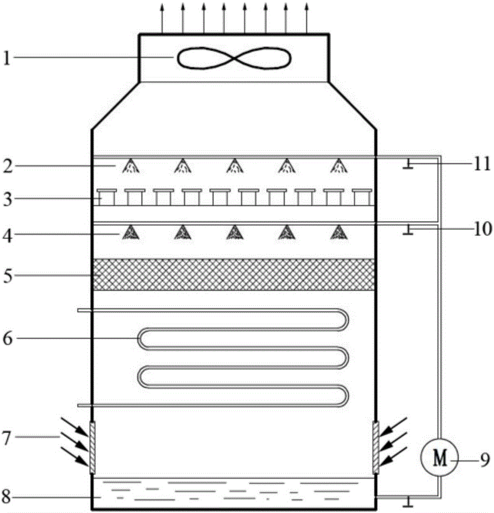
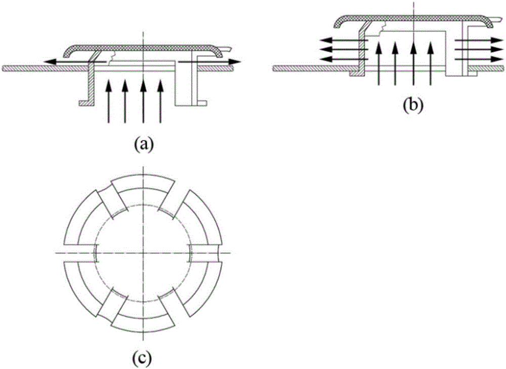
[0023] Embodiment 1: A water-saving and fog-eliminating closed cooling tower with a floating valve structure. The tower body is respectively equipped with a fan system 1, a spray system 2, a float valve element 3, a spray system 4, and a packing part from top to bottom. 5. Cooling coil 6, air inlet 7, reservoir 8; floating valve components in the tower such as figure 2 Material shown is copper. The float valve element 3 is located below the spray system 2 on the top of the tower, and above the lower spray system 4 and the packing part; the operation process: the spray water enters the upper and lower spray systems 2 and the upper and lower spray systems from the tank 8 at the bottom of the tower through the spray pump 9 4, and set the floating valve element 3 in the middle of the upper and lower spraying systems. After the spray water is evenly distributed by the filler 5, it is sprayed on the surface of the coil 6; the fan 1 on the top of the tower rotates to generate negat...

Embodiment 2

[0024] Embodiment 2: A water-saving and fog-eliminating closed cooling tower with a floating valve structure. The tower body is respectively equipped with a fan system 1, a spray system 2, a float valve element 3, a spray system 4, and a packing part from top to bottom. 5. Cooling coil 6, air inlet 7, reservoir 8; floating valve components in the tower such as figure 2 The material shown is made of PVC / PP, and the float valve element 3 is located below the spray system 2 on the top of the tower, and above the lower spray system 4 and the packing part; the operation process: the spray water passes through the spray pump 9 and is stored at the bottom of the tower The pool 8 enters the upper and lower spray systems 2 and 4, and a float valve element 3 is arranged in the middle of the upper and lower spray systems. After the spray water is evenly distributed by the filler 5, it is sprayed on the surface of the coil 6; the fan 1 on the top of the tower rotates to generate negative...


PUM


Abstract

The invention discloses a water-saving fog-dissipation closed cooling tower with a float valve structure. The cooling tower is internally provided with a draught fan system, an upper spray system, float valve elements, a lower spray system, a filler part, a cooling coil, an air inlet system and a water storage pool; each float valve element is a tower plate provided with the float valve structure and is placed between the upper spray system and the lower spray system of the closed cooling tower; after being subjected to heat transfer with the coil and a filler and then passes through the float valve structure, hot humid air is subjected to heat and mass transfer with spray water of the upper spray system again, accordingly, the temperature and the moisture content of the air at an outlet of the closed cooling tower are decreased, and the water saving and fog dissipation purposes are achieved. By means of the water-saving fog-dissipation closed cooling tower, heat and mass transfer between the spray water and the air at the outlet can be strengthened, the temperature and the moisture content of the air at an outlet are decreased, and fog plumes at the top of the closed cooling tower are relieved or removed to a certain extent; and the closed cooling tower has the advantages of being capable of saving energy and water, good in heat transfer effect, simple in structure, easy to maintain and the like.

Description

technical field [0001] The invention belongs to the technical field of cooling tower equipment, and in particular relates to a water-saving and fog-eliminating closed cooling tower with a floating valve structure. Background technique [0002] Cooling towers use evaporative cooling technology to remove a large amount of heat from circulating water. Generally, cooling towers are divided into open cooling towers and closed cooling towers. Compared with the open cooling tower, the industrial medium of the closed cooling tower flows in the coil, which avoids the industrial medium from being polluted by spray cooling water and air, so as to keep the industrial medium clean. However, the closed cooling tower is the same as the open cooling tower. The evaporation loss of the spray cooling water is huge and cannot be ignored. At the same time, the concentration of the spray water evaporates and its concentration continues to increase, resulting in serious fouling on the surface of...

Claims


Application Information

Patent Timeline
IPC IPC(8): F28C1/00F28D5/02
CPCF28C1/00F28D5/02
Inventor 陈清林谢晓翠张艺何畅张冰剑徐涛高学农
Owner SUN YAT SEN UNIV
Why Eureka
Try Eureka