
Dehumidifier

A dehumidifier and wet zone technology, applied in the field of air treatment, can solve the problems of weakening the dehumidification effect, affecting the air supply volume, and not being able to send out all the bottom of the air duct, and achieving good dehumidification and mildew prevention effect, low manufacturing cost, and excellent dehumidification effect. Effect

Pending Publication Date: 2017-04-26
GUANGDONG FUXIN ELECTRONICS TECH
View PDF8 Cites 5 Cited by
  • Summary
  • Abstract
  • Description
  • Claims
  • Application Information

AI Technical Summary

Problems solved by technology

However, the air circulation of the existing dehumidifiers mostly uses the horizontal air outlet method to supply air. Because the cold air tends to settle, the current air outlet method of the dehumidifier is likely to prevent all the air from the bottom of the air duct, which affects the air supply. amount, thus weakening the dehumidification effect

Method used


Image

  • Dehumidifier

Examples


Embodiment Construction

[0017] The specific implementation of the present invention will be described below in conjunction with the accompanying drawings of the present invention. Obviously, the described specific implementation is only a part of the embodiments. Other embodiments obtained below are all within the protection scope of the present invention.

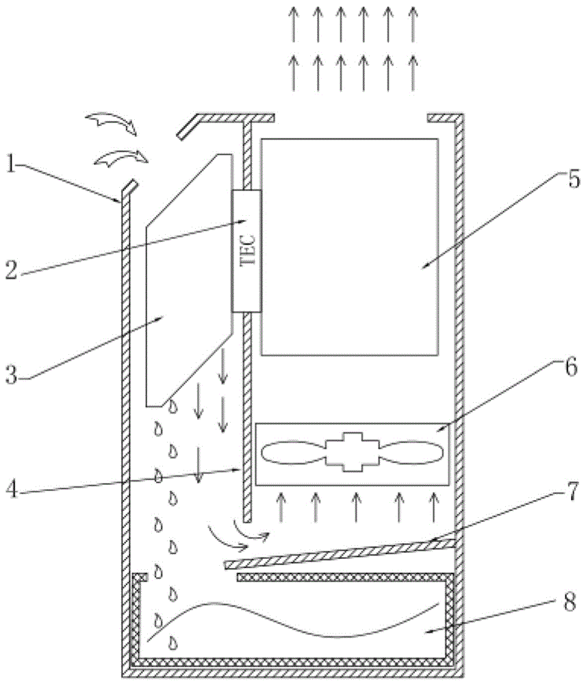
[0018] see figure 1 , the dehumidifier of the present invention includes a housing 1, a partition plate 4 is arranged inside the housing to divide the housing into a dehumidification area and a heat dissipation area, a control circuit board, a semiconductor refrigeration chip 2, a cold pole, a heat sink of the semiconductor refrigeration chip The poles are respectively attached to the cold end heat exchanger 3 and the hot end heat exchanger 5. The bottom of the shell is provided with a water receiving box 8. The dehumidification area and the heat dissipation area are left and right structures. The fan 6 is installed in the heat dissipation area. ...


PUM


Abstract

The invention discloses a dehumidifier. The dehumidifier comprises a shell. A separating plate used for dividing the shell into a dehumidification area and a heat radiation area, a control circuit board and a semiconductor refrigeration chip are arranged in the shell. A cold pole and a hot pole of the semiconductor refrigeration chip are tightly attached to a cold end heat exchanger and a hot end heat exchanger correspondingly. A water receiving box is arranged at the bottom of the shell. The dehumidification area and the heat radiation area are of a left-right structure. A fan is arranged in the heat radiation area. Dehumidified dry cold air enters the heat radiation area from a bottom end air opening of the separating plate and leaves from a top air outlet of the shell. The dehumidifier adopts a dehumidification mode of exhausting air upwards from the bottom, and not only can rapidly remove moisture in the air, but also is large in dry air outlet amount and excellent in dehumidification effect.

Description

technical field [0001] The invention relates to the technical field of air treatment, and more specifically relates to a dehumidifier. Background technique [0002] Dehumidification is to remove excess water vapor in the air according to the requirements of water vapor content in the air in life or production. The principle is to condense excess water vapor in the air into water through a dehumidifier, so as to reduce the moisture content of the air and make it meet the requirements. At present, there are two commonly used methods of household dehumidification: one is physical adsorption dehumidification, and the other is electronic refrigeration dehumidification. Physical adsorption dehumidification is the use of chemical absorbents or desiccants to absorb water molecules in the air to reduce air humidity. After a period of use, it will fail due to moisture absorption or chemical reactions. In contrast, electronic refrigeration dehumidification has obvious advantages becau...

Claims


Application Information

Patent Timeline
Patent Type & Authority Applications(China)
IPC IPC(8): F24F5/00F24F11/02F24F13/22
CPCF24F5/0042F24F13/222F24F11/89
Inventor 高俊岭罗嘉恒胡文邦
Owner GUANGDONG FUXIN ELECTRONICS TECH
Learn More