
Magnetic unit vertical combination method of permanent magnetic spreader

A combination method and spreader technology, applied in the directions of permanent magnets, load hanging elements, magnets, etc., can solve the problems of difficult drilling, high comprehensive cost, and high manufacturing cost.

Inactive Publication Date: 2017-04-26
YUEYANG YONGJIN ELEVATORING PERMANENT MAGNET
View PDF10 Cites 1 Cited by
  • Summary
  • Abstract
  • Description
  • Claims
  • Application Information

AI Technical Summary

Problems solved by technology

This scheme is widely used at present, but due to the complicated process, high manufacturing cost and expensive
[0005] The process of traditional permanent magnet spreader is complex and complex
The inner and outer magnetic poles need to be processed through multiple processes such as turning, drilling, planing, and milling. The outer plate is made of manganese steel, which is difficult to process and drill, resulting in high overall costs.

Method used


Image

  • Magnetic unit vertical combination method of permanent magnetic spreader
  • Magnetic unit vertical combination method of permanent magnetic spreader
  • Magnetic unit vertical combination method of permanent magnetic spreader

Examples


Embodiment Construction

[0024] The following will clearly and completely describe the technical solutions in the embodiments of the present invention with reference to the drawings in the embodiments of the present invention.

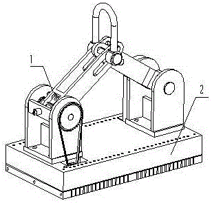
[0025] Examples of the present invention figure 1 As shown, it includes a combination of a lifting system 1 and a magnetic system 2; the magnetic system 2 is arranged at the lower part of the lifting system 1.

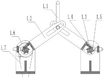
[0026] Hanging system 1 such as figure 2 As shown, a shackle 1.1 is provided; the shackle 1.1 is connected with the left and right booms 1.2; the left and right booms 1.2 are respectively provided with a ratchet shaft 1.3; the ratchet shaft 1.3 is provided with a pawl 1.4, a ratchet wheel 1.5 and a large sprocket 1.6, A chain 1.7 is provided on the large sprocket 1.6. The shackle 1.1 moves up and down, which drives the boom 1.2 to move up and down, and then drives the ratchet shaft 1.3 to rotate, and then drives the ratchet wheel 1.5 and the pawl 1.4 to move, and th...


PUM


Abstract

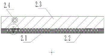
The invention discloses a magnetic unit vertical combination method of a permanent magnetic spreader. The magnetic unit vertical combination method is characterized in that a magnetic system of the permanent magnetic spreader is arranged into an upper layer, a middle layer, a lower layer and a shaft transmission system, wherein the upper layer is a thick iron plate which can communicate with a magnetic path; the middle layer is a movable permanent magnet unit; the lower layer is a longitudinally arranged permanent magnet unit; external force can enable the middle layer magnet to tangentially move through the shaft transmission system so as to reach switching between a magnetizing state and a demagnetizing state; as the magnetic field directions of the middle layer permanent magnets and the lower layer permanent magnets to be mutually perpendicular, when the middle layer permanent magnets move a pitch, the middle layer and the lower layer can have two states same as or opposite to each other in magnetic field directions, i.e. the state of magnetizing or demagnetizing occurs on the working surface of the permanent magnetic spreader, so that the advantages of the circulating magnetizing and demagnetizing of the traditional permanent magnetic spreader can be kept, the benefit of greatly reducing the processing cost during production manufacturing can also be obtained; and meanwhile, as the magnets tangentially move, the magnetizing resistance and demagnetizing resistance are much weaker than those of the traditional spreader, the problem of non-synchronous single machine can be solved, and use is more flexible and convenient.

Description

technical field [0001] The invention relates to the technical field of magnetic force application, in particular to a vertical combination method of magnetic force units of a permanent magnet hanger. Background technique [0002] The permanent magnet lifter is to use the magnetic force of the permanent magnet to lift the iron and steel workpiece. The key technology is to solve how to magnetize and demagnetize. If the cycle of magnetization and degaussing cannot be realized, the workpiece cannot be lifted and unloaded, and no matter how strong the magnetic force is, it is meaningless. [0003] The early permanent magnet spreader adopted the technical scheme of ejector rod to unload forcibly. That is, the ejector mechanism is used to forcibly push away the sucked workpiece. When unloading, although the sucked workpiece is pushed away, the working surface of the spreader still has magnetic force. [0004] Later permanent magnet hoists began to adopt the technical solution of...

Claims


Application Information

Patent Timeline
Patent Type & Authority Applications(China)
IPC IPC(8): B66C1/04H01F7/02
CPCB66C1/04H01F7/0257
Inventor 黄伟良任杰
Owner YUEYANG YONGJIN ELEVATORING PERMANENT MAGNET
Learn More