Magnetic gear

A technology of magnetic gears and gear bodies, applied in the field of magnetic gears, can solve problems such as meshing dislocation, damaged gears, and inability to adapt to gear transmission.

Active Publication Date: 2019-08-09
ZHUHAI PANSHI ELECTRONICS TECH CO LTD
View PDF6 Cites 0 Cited by
  • Summary
  • Abstract
  • Description
  • Claims
  • Application Information

AI Technical Summary

Problems solved by technology

However, this gear is only suitable for gear transmission at low speeds, and cannot adapt to high-speed gear transmission.
If high-speed transmission is carried out, it is easy to cause meshing misalignment and damage the gears

Method used


Image

  • Magnetic gear
  • Magnetic gear
  • Magnetic gear

Examples


no. 1 Embodiment

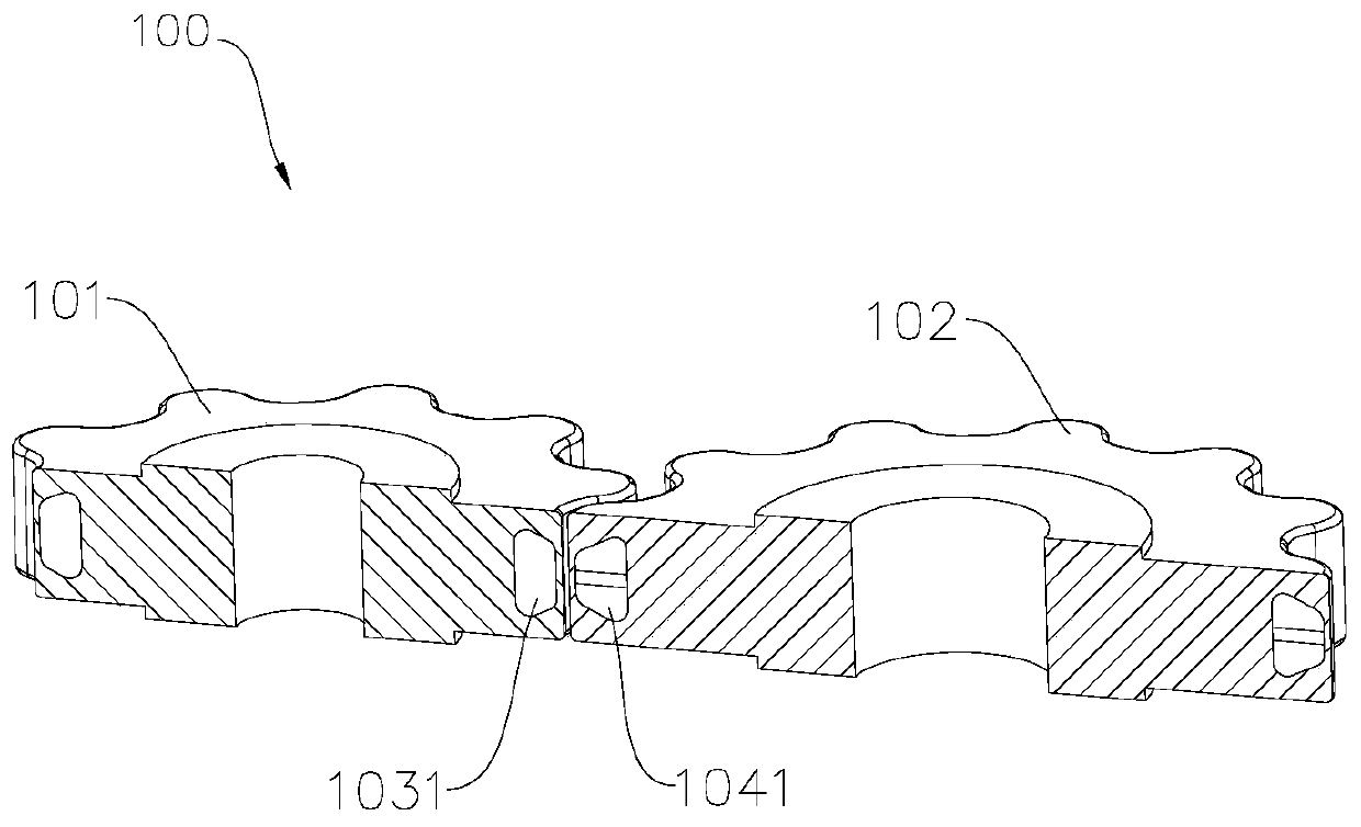
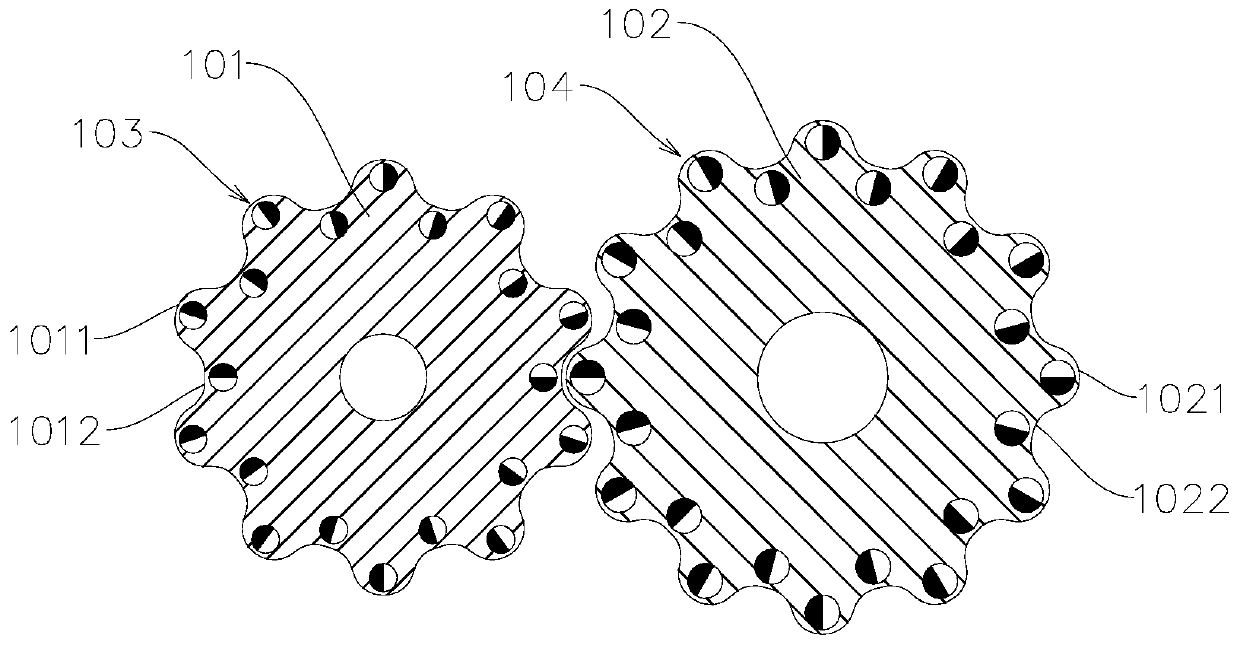
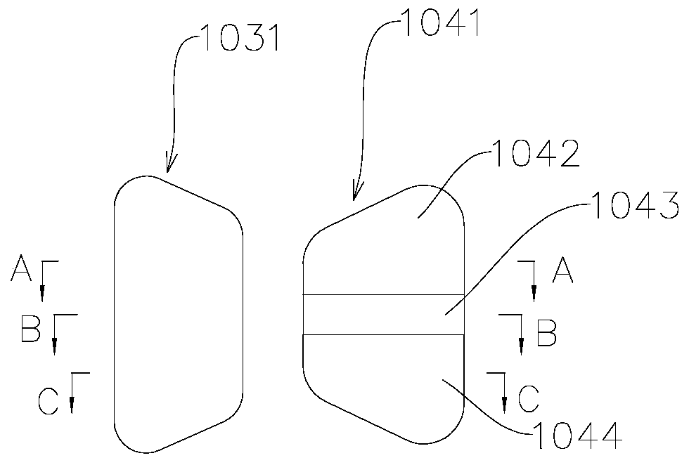
[0031] according to figure 1 , figure 2 , image 3 In a comprehensive analysis, the magnetic gear 100 includes a gear body and a magnetic source. The gear body includes a first gear body 101 and a second gear body 102 , the diameter of the first gear body 101 is smaller than the diameter of the second gear body 102 . Preferably, the diameter of the first gear body 101 is about half of the diameter of the second gear body 102 . First magnetic source arrays 103 are uniformly distributed along the circumferential direction of the first gear body 101 , and second magnetic gear arrays 104 are uniformly distributed along the circumferential direction of the second gear body 102 . The first magnetic source 1031 of the first magnetic source array 103 is distributed near the outer side of the first gear body 101 , and the second magnetic source 1041 of the second magnetic source array 104 is distributed near the outer side of the second gear body 102 . The magnetization direction ...


PUM


Abstract

The invention provides a magnetic gear comprising gear bodies and magnetic sources. The gear bodies comprise a first gear body and a second gear body. A first magnetic source array is uniformly distributed along the circumferential direction of the first gear body, and a second magnetic source array is uniformly distributed along the circumferential direction of the second gear body. The middle parts of the first magnetic source of the first magnetic source array and the second magnetic source of the second magnetic source array cooperate to generate attraction force along the axial directionof the gear bodies. The two ends of the first magnetic source and the second magnetic source cooperate to generate repulsive force respectively. The repulsive force and the attraction force are simultaneously generated between the magnetic sources on the working position. The driving force of the driving gear for driving the driven gear to rotate is improved by generating the repulsive force on both ends of the magnetic sources, and the transmission stability between the gears is improved. The phase alignment in case of engaging between the gears can be realized through the attraction force generated in the middle of the magnetic sources, and the engaging reliability of the gears can be improved.

Description

technical field [0001] The invention relates to a novel magnetic gear. Background technique [0002] In the traditional transmission area, mechanical gear is the most widely used transmission mechanism. Traditional gears rely on the meshing of their respective teeth for transmission, but mechanical gears have many disadvantages, such as vibration, loss, periodic lubrication, etc., which often limit the further improvement of the performance of the transmission system. For this reason, magnetic gears appear in the transmission system, which are used to replace the work of mechanical gears to a certain extent. [0003] The magnetic gears that appear today have several pairs of N and S magnetic poles alternately distributed on the surface of the gear annular cylinder, and the transmission between the gears is carried out by using a single pole between the magnetic poles. However, this kind of magnetic gear has a low bearing capacity and cannot adapt to higher transmission spe...

Claims


Application Information

Patent Timeline
Patent Type & Authority Applications(China)
IPC IPC(8): H02N11/00
CPCH02N11/006
Inventor 何春旺
Owner ZHUHAI PANSHI ELECTRONICS TECH CO LTD
Why Eureka
Try Eureka