Infinitely variable transmission with multiple motors connected in series

A continuously variable transmission, multi-motor technology, applied in the transmission field, can solve the problems of non-compliance with new energy requirements, complex engine manufacturing, poor battery life, etc.

Active Publication Date: 2017-04-26
SHENZHEN WORLD WIDE NEW ENERGY TECH CO LYD
View PDF7 Cites 1 Cited by
  • Summary
  • Abstract
  • Description
  • Claims
  • Application Information

AI Technical Summary

Problems solved by technology

[0004] 1. For gasoline / diesel vehicles, the transmission technology is mature, and the high speed is still powerful, but the low speed consumes fuel, the engine manufacturing is complicated, and it does not meet the requirements of new energy;
[0005] 2. At present, for pure electric vehicles, the engine technology is not mature enough, the car with gearbox is too expensive, the battery life is not good, and the low-end gearbox is too noisy; the motor is powerful at low speed, but weak at high speed. Generally, electric vehicle technology wastes more energy. , it needs to be equipped with a large battery pack, which cannot meet the popularization requirements;
[0006] 3. Hybrid power, with electricity at low speeds and oil at high speeds, a good combination, but there is still a sense of frustration when shifting gears. Two sets of control systems for one car cost too much and are difficult to popularize

Method used


Image

  • Infinitely variable transmission with multiple motors connected in series
  • Infinitely variable transmission with multiple motors connected in series
  • Infinitely variable transmission with multiple motors connected in series

Examples


Embodiment

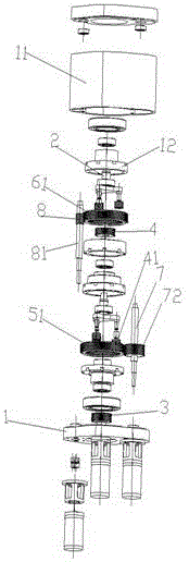
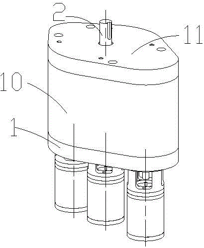
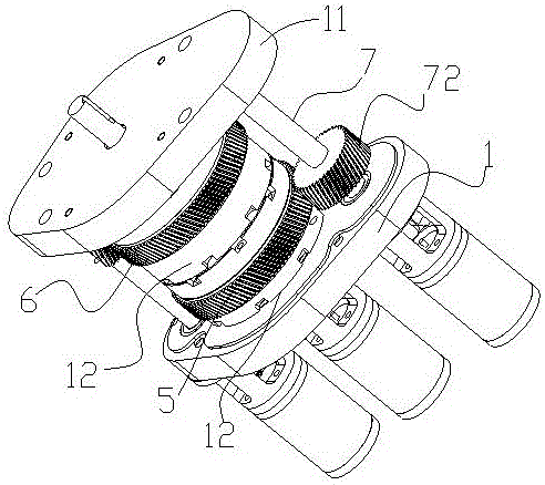
[0026] Such as Figure 1 to Figure 7 As shown, the multi-motor series continuously variable transmission provided by the present invention includes a base 1, an upper cover plate 11, and an outer shield 10, and the base 1 and the upper cover plate 11 are respectively installed on the two ends of the outer shield 10 to form an accommodating cavity, the upper cover plate 11 is provided with an output shaft 2 as an output end, and the accommodating cavity is provided with a main shaft rotation system for driving the output shaft and a plurality of side motor planetary drive systems; the main shaft rotation system includes a coaxially arranged lower planet Frame 13, the upper planet carrier 14 fixed with the above-mentioned output shaft, the first sun gear 3 located below the lower planet carrier, and the second sun gear 4 installed at the upper end of the lower planet carrier, the lower end of the first sun gear 3 is provided with a rotating shaft , the rotating shaft is set in t...


PUM


Abstract

The invention discloses an infinitely variable transmission with multiple motors connected in series. The infinitely variable transmission is characterized by comprising a base, an upper cover plate and an outer shield; the base and the cover plate are mounted at the two ends of the outer shield correspondingly; the base, the cover plate and the outer shield form a containing cavity; an output shaft serving as an output end is arranged on the upper cover plate; a main shaft rotating system driving the output shaft and two or more collateral planet driving systems are arranged in the containing cavity; the main variable transmission adopts a planetary structure, outer ring structure teeth and a coaxial bearing are added, the power and speed of a central motor and an outer motor are coupled on one shaft through a special structure and are coupled together layer by layer in a multistage mode; and the special structure ensures that tooth phases do not need to be separated, and the multiple motors can be divided to work independently and also united smoothly to work. The technology can be applied to the situation that one or more motors are coupled together in a stepless mode, multiple controlling modes of speed change are realized, and the three key requirements, namely high speed, smooth-going and energy-saving, of new-energy automobile super engines can be met in combination with the characteristics of a hollow-cup motor. The product further can be applied to collecting a great amount of small energy for integration, such as wind electricity integration and small hydropower station integration.

Description

technical field [0001] The invention relates to a gearbox, in particular to a multi-motor series stepless gearbox. Background technique [0002] The core technology of electric vehicles is battery technology and engine technology, but everyone ignores the hardware research and development of gearboxes. You can often read on the Internet what new battery materials have been invented by a certain university, which is several times larger than the current battery capacity. (Of course, these are still far from real mass production), and I have never seen that a certain university has manufactured a new type of engine. The key lies in the engine, and the key to the engine is the gearbox. The quality of the engine gearbox determines the performance of the car. [0003] The present invention compares prior art: [0004] 1. For gasoline / diesel vehicles, the transmission technology is mature, and the high speed is still powerful, but the low speed consumes fuel, the engine manufact...

Claims


Application Information

Patent Timeline
Patent Type & Authority Applications(China)
IPC IPC(8): B60K17/08B60K17/12
CPCB60K17/08B60K17/12
Inventor 刘身谦
Owner SHENZHEN WORLD WIDE NEW ENERGY TECH CO LYD
Why Eureka
Try Eureka