
Vacuum tube flash structure and manufacturing method thereof

A manufacturing method and technology of vacuum tubes, applied in semiconductor/solid-state device manufacturing, semiconductor devices, electrical components, etc., to achieve good programming results

Inactive Publication Date: 2017-04-19
ZING SEMICON CORP
View PDF6 Cites 13 Cited by
  • Summary
  • Abstract
  • Description
  • Claims
  • Application Information

AI Technical Summary

Problems solved by technology

The speed of electrons in vacuum is theoretically 3×10 10 cm / s, but only 5×10 in semiconductors 7 cm / s

Method used


Image

  • Vacuum tube flash structure and manufacturing method thereof
  • Vacuum tube flash structure and manufacturing method thereof
  • Vacuum tube flash structure and manufacturing method thereof

Examples


Embodiment Construction

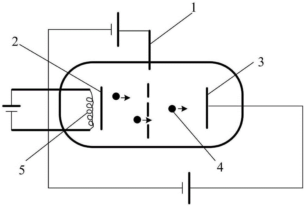
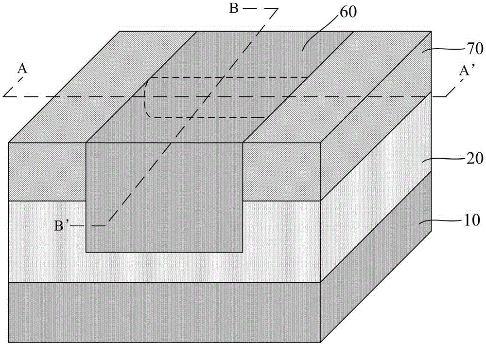
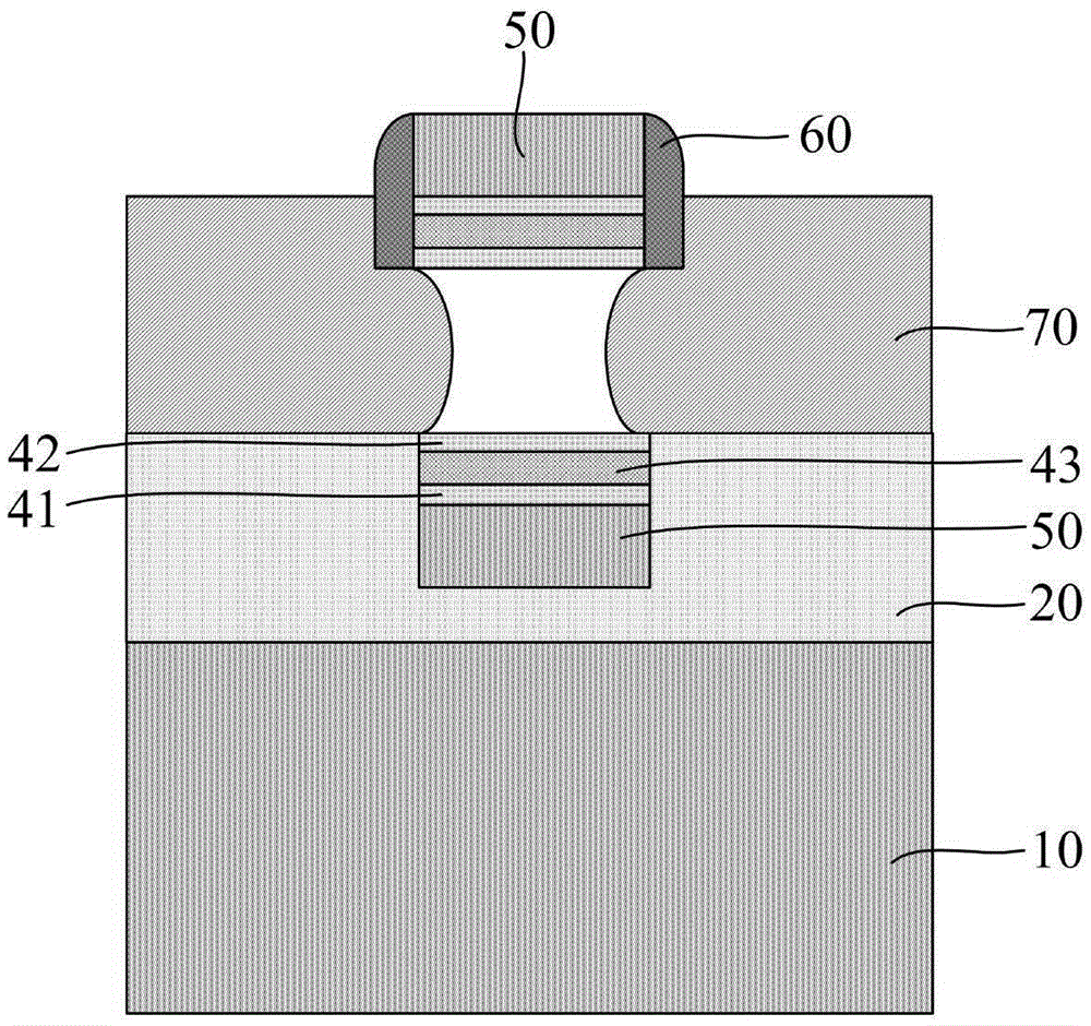
[0039] The vacuum tube flash memory structure of the present invention and its manufacturing method will be described in more detail below in conjunction with schematic diagrams, wherein a preferred embodiment of the present invention is shown, and it should be understood that those skilled in the art can modify the present invention described here and still implement the present invention beneficial effect. Therefore, the following description should be understood as the broad knowledge of those skilled in the art, but not as a limitation of the present invention.

[0040] In the interest of clarity, not all features of an actual implementation are described. In the following description, well-known functions and constructions are not described in detail since they would obscure the invention with unnecessary detail. It should be appreciated that in the development of any actual embodiment, numerous implementation details must be worked out to achieve the developer's specifi...


PUM


Abstract

The invention provides a vacuum tube flash structure and a manufacturing method thereof. Vacuum is formed in a channel, and an oxide-nitride-oxide combined structure serves as a gate medium layer, wherein the nitride can better restrict electric charges, so as to provide insulation blocking effect between a grid electrode and vacuum. Since the oxide-nitride-oxide combined structure serves as a gate medium layer, a formed device has better programming, erasing speed and storage time. The grid electrode control performance can be improved, and the grid electrode current leakage can be minimized.

Description

technical field [0001] The invention relates to the field of semiconductor manufacturing, in particular to a vacuum tube flash memory structure and a manufacturing method thereof. Background technique [0002] A vacuum tube (English: Vacuum Tube) is an electronic component that controls the flow of electrons in a circuit. The electrodes involved in the work are packaged in a vacuum container (the tube walls are mostly glass), hence the name. Before the middle of the 20th century, because semiconductors were not yet popular, basically all electronic equipment at that time used vacuum tubes, which formed the demand for vacuum tubes at that time. However, with the development, popularization and civilianization of semiconductor technology, vacuum tubes were finally replaced by semiconductors due to reasons such as high cost, durability, large size, and low efficiency. But you can see vacuum tubes in high-frequency transmitters in stereos, microwave ovens, and satellites. In ...

Claims


Application Information

Patent Timeline
Patent Type & Authority Applications(China)
IPC IPC(8): H01L27/115H01L21/28H01L29/10H10B69/00
CPCH01L29/40117H01L29/1025H10B41/00H10B43/00H01L21/31144H01L29/66833H01L29/792H10B43/30H01L21/31111H01L21/32134H01L21/324H01L29/408H01L29/4234
Inventor 肖德元张汝京
Owner ZING SEMICON CORP
Learn More