
A kind of programming test method of phase change memory

A phase change memory and phase change storage technology, which is applied in the field of programming and testing of phase change memory, and can solve problems such as data operation failure

Active Publication Date: 2020-06-09
SEMICON MFG INT (SHANGHAI) CORP +1
View PDF4 Cites 0 Cited by
  • Summary
  • Abstract
  • Description
  • Claims
  • Application Information

AI Technical Summary

Problems solved by technology

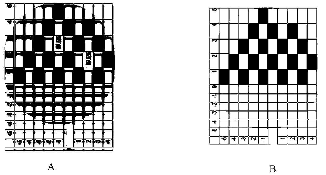
But the 1T1R test yield distribution chart shows that almost all data operations fail, even the output current of 1T is greater than 3mA

Method used


Image

  • A kind of programming test method of phase change memory
  • A kind of programming test method of phase change memory
  • A kind of programming test method of phase change memory

Examples


Embodiment 1

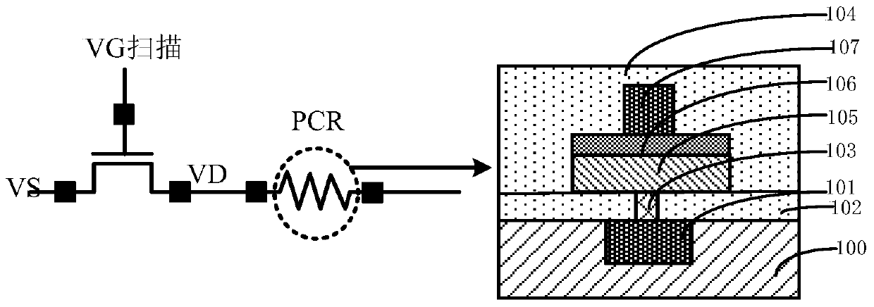
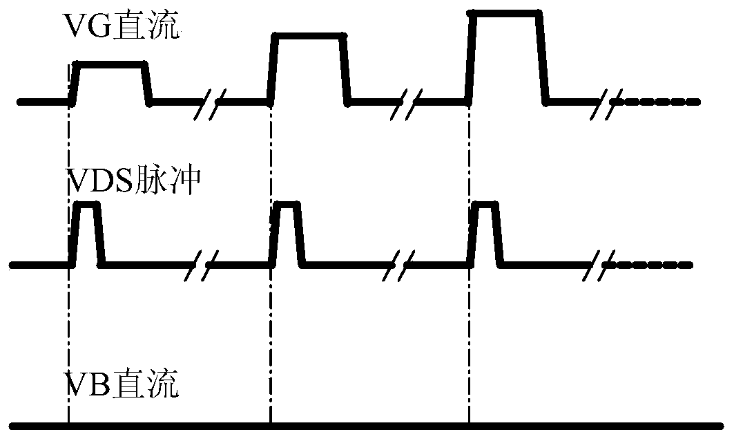
[0037] In order to solve the problems in the prior art, the present invention provides a programming and testing method of phase change memory, and the method of the present invention will be further described below in conjunction with the accompanying drawings. in, figure 1 It is a structural schematic diagram of the programming and testing method of the phase change memory described in a specific embodiment of the present invention; figure 2 It is a schematic diagram of the voltage in the programming and testing method of the phase change memory described in a specific embodiment of the present invention; image 3 It is the yield distribution diagram of the programming test method of phase change memory, wherein A is the yield distribution diagram of the programming test method of phase change memory in the present invention, and B is the yield distribution of the programming test method of phase change memory in the prior art picture.

[0038] The invention discloses a p...

Embodiment 2

[0066] In order to solve the problems in the prior art, the present invention provides a method for programming and testing phase change memory. The method of the present invention will be further described below in conjunction with the accompanying drawings. in, figure 1 It is a structural schematic diagram of the programming and testing method of the phase change memory described in a specific embodiment of the present invention; figure 2 It is a schematic diagram of the voltage in the programming and testing method of the phase change memory described in a specific embodiment of the present invention; image 3 It is the yield distribution diagram of the programming test method of phase change memory, wherein A is the yield distribution diagram of the programming test method of phase change memory in the present invention, and B is the yield distribution of the programming test method of phase change memory in the prior art picture.

[0067] The invention discloses a meth...


PUM


Abstract

The invention provides a programming test method for a phase change memory. The phase change memory comprises a transistor and a phase change memory resistor unit. A drain electrode of the transistor is electrically connected to the phase change memory resistor unit. The method comprises S1: applying direct current voltage to a grid electrode of the transistor to turn on the transistor and applying pulse voltage to a drain electrode of the transistor to operate the phase change memory, and S2: applying direct voltage VG to the grid electrode of the transistor to turn on the transistor, simultaneously, applying direct voltage DC to the drain electrode to perform reading operation and measuring the resistance of the phase change storage resistor unit. The method realizes the pressure drop of the drain electrode of the transistor so that the transistor has large load resistance, the current flows from the transistor to the phase change material layer, and the measurement of the resistance of the phase change storage resistor unit is realized.

Description

technical field [0001] The invention relates to the field of semiconductors, and in particular, the invention relates to a programming and testing method of a phase-change memory. Background technique [0002] With the development of information technology, especially the popularity of mobile phones and other portable electronic devices, the application of non-volatile memory chips has penetrated into all aspects of modern human life. Flash memory (Flash Memory), as a typical non-volatile memory, has made great progress in the past ten years, but after the semiconductor technology enters the 22nm node, the flash memory technology based on floating gate charge storage has encountered difficulties in size reduction. difficulty. At this time, PCRAM (Phase Change Random Access Memory) technology has great advantages over flash memory technology in many aspects such as cell area, read and write speed, read and write times, and data retention time. Wide range of applications. ...

Claims


Application Information

Patent Timeline
Patent Type & Authority Patents(China)
IPC IPC(8): G11C29/56
Inventor 李莹詹奕鹏
Owner SEMICON MFG INT (SHANGHAI) CORP
Learn More