An adaptive waveform transmission method, device and system
A waveform transmission and self-adaptive technology, applied in transmission systems, digital transmission systems, baseband system components, etc., can solve problems such as the inability to meet the needs of the scene and the inability to adaptively configure the waveform transmission scheme.
- Summary
- Abstract
- Description
- Claims
- Application Information
AI Technical Summary
Problems solved by technology
Method used
Image

Examples
Embodiment 1
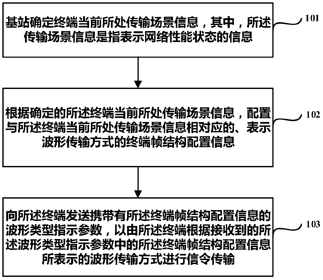
[0079] Embodiment 1 of the present invention provides an adaptive waveform transmission method, which is applicable to filter bank multi-carrier systems, such as figure 1 As shown, it is a schematic flowchart of the adaptive waveform transmission method described in Embodiment 1 of the present invention, and the method may include the following steps:
[0080] Step 101: the base station determines the transmission scene information where the terminal is currently located, where the transmission scene information refers to information indicating network performance status.
[0081] It should be noted that the network performance status can be represented by high latency, slow movement, small capacity, low latency, high speed mobility, or large capacity. Therefore, different network performance states can be represented by different transmission scene information. The embodiment of the invention does not repeat this.
[0082] Step 102: According to the determined transmission s...
Embodiment 2
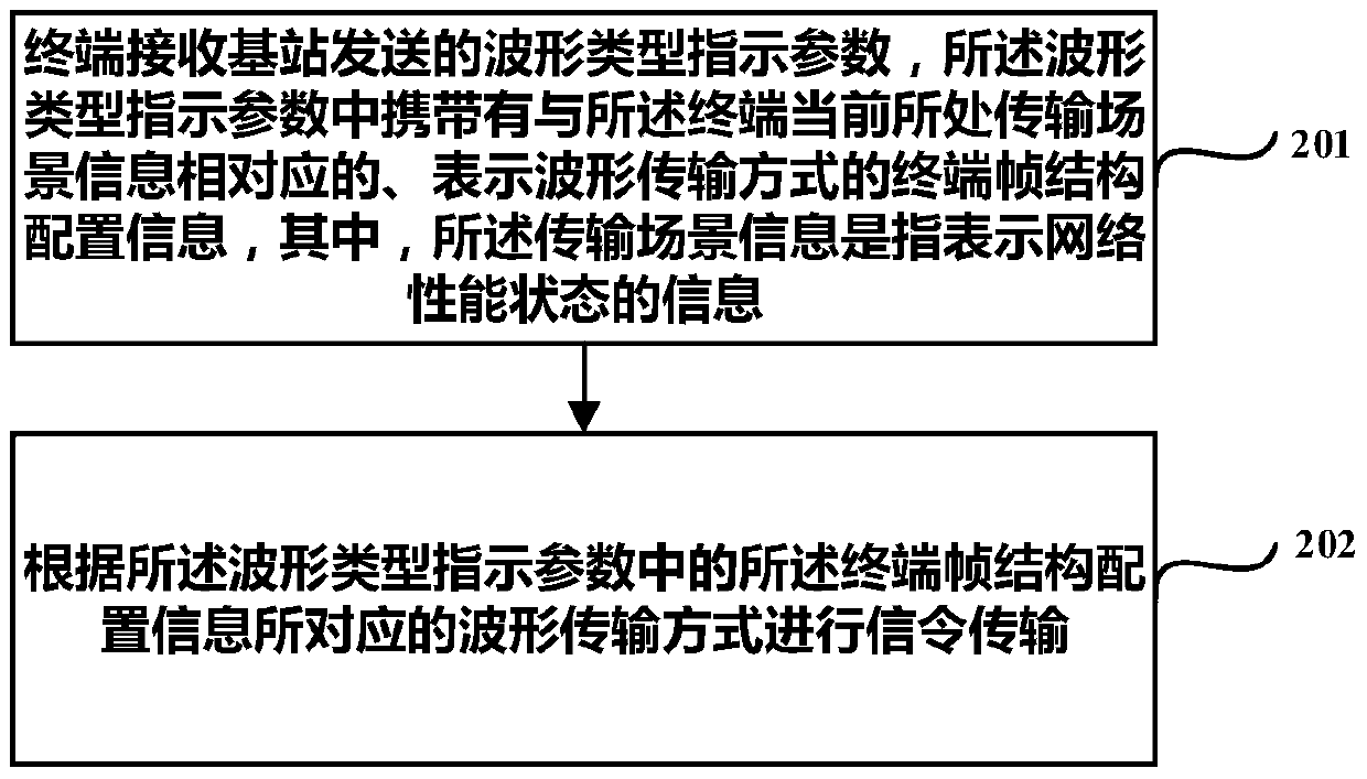
[0117] Embodiment 2 of the present invention takes the action executing party as a terminal as an example to further describe the adaptive waveform transmission method described in Embodiment 1 of the present invention. This method is applicable to a filter bank multi-carrier system, such as figure 2 As shown, it is a schematic flowchart of the adaptive waveform transmission method described in Embodiment 2 of the present invention, and the method may include the following steps:
[0118] Step 201: The terminal receives the waveform type indication parameter sent by the base station, the waveform type indication parameter carries the terminal frame structure configuration information corresponding to the current transmission scene information of the terminal and indicating the waveform transmission mode, wherein the The above transmission scenario information refers to information representing a network performance status.
[0119] It should be noted that the network performa...
Embodiment 3
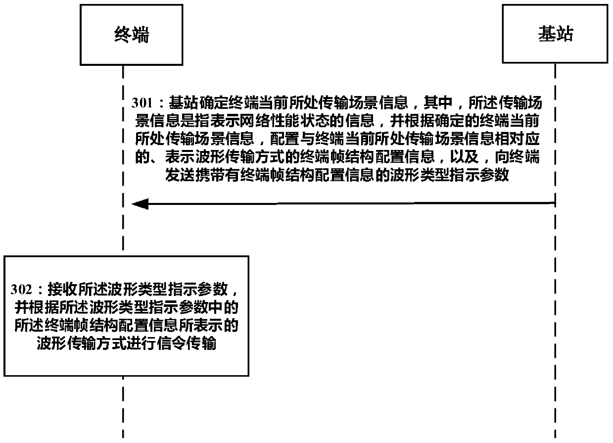
[0136] Embodiment 3 of the present invention takes interactive execution between a base station and a terminal as an example to further describe the adaptive waveform transmission method described in Embodiments 1 to 2 of the present invention, as follows image 3 As shown, it is a schematic flowchart of the adaptive waveform transmission method described in Embodiment 3 of the present invention, and the method may include the following steps:
[0137] Step 301: The base station determines the transmission scene information where the terminal is currently located, wherein the transmission scene information refers to information indicating the network performance status, and according to the determined transmission scene information where the terminal is currently located, configure The terminal frame structure configuration information corresponding to the transmission scene information representing the waveform transmission mode, and the waveform type indication parameter carr...
PUM
 Abstract
Description
Claims
Application Information
 - Generate Ideas
- Intellectual Property
- Life Sciences
- Materials
- Tech Scout
- Unparalleled Data Quality
- Higher Quality Content
- 60% Fewer Hallucinations
Browse by: Latest US Patents, China's latest patents, Technical Efficacy Thesaurus, Application Domain, Technology Topic, Popular Technical Reports.
© 2025 PatSnap. All rights reserved.Legal|Privacy policy|Modern Slavery Act Transparency Statement|Sitemap|About US| Contact US: help@patsnap.com