
Touch switch interlocking configuration method

A technology of touch switch, configuration method, applied in the direction of electronic switch, program control, comprehensive factory control, etc.

Active Publication Date: 2017-03-29
HUNAN UNIV OF TECH
View PDF16 Cites 2 Cited by
  • Summary
  • Abstract
  • Description
  • Claims
  • Application Information

AI Technical Summary

Problems solved by technology

[0003] In order to solve the problems existing in the control of two or more locations of existing switches, the present invention provides a touch switch interlock configuration method, which is realized by connecting a computer in a distributed wireless communication network to configure a wireless networking touch switch

Method used


Image

  • Touch switch interlocking configuration method
  • Touch switch interlocking configuration method
  • Touch switch interlocking configuration method

Examples


Embodiment Construction

[0023] The present invention will be further described below in conjunction with accompanying drawing.

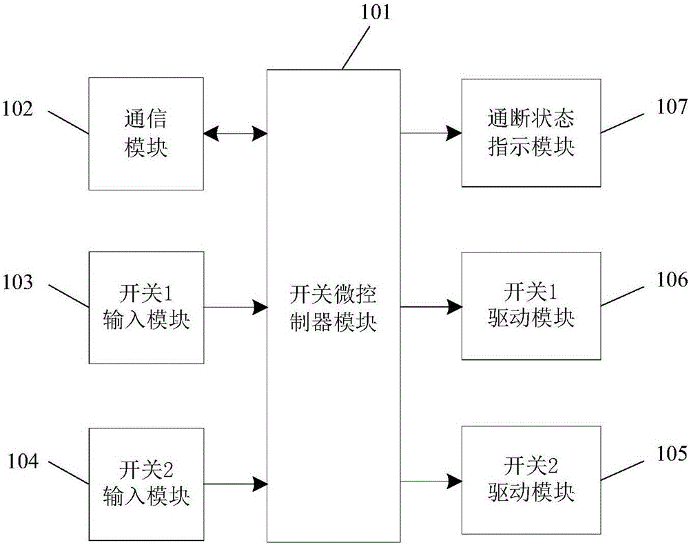
[0024] Such as figure 1 Shown is a structure diagram of an embodiment of a wireless networking touch switch, including a switch microcontroller module 101, a communication module 102, a switch 1 input module 103, a switch 2 input module 104, a switch 1 driving module 105, a switch 2 driving module 106, a communication module Break indication module 107. The communication module 102, the switch 1 input module 103, the switch 2 input module 104, the switch 1 drive module 105, the switch 2 drive module 106, the on-off indication module 107 and the switch microcontroller module 101 are electrically connected or have photoelectric isolation The electrical connection relationship is used for the transmission of related signals.

[0025] The function of the switch micro-controller module 101 includes: judging and identifying the state and operation of the switch 1 input module 1...


PUM


Abstract

Disclosed is a touch switch interlocking configuration method. A computer is connected to a distributed wireless communication network to configure wirelessly-networked touch switches. Each wirelessly-networked touch switch comprises a switch microcontroller module, a communication module, a plurality of pairs of switch input modules and switch drive modules, and the like. The multiple wirelessly-networked touch switches and other function distribution units configured on demand constitute a control system through the distributed wireless communication network, which is flexible and convenient. The electric switches in the multiple wirelessly-networked touch switches can be arbitrarily configured to realize local-remote control or multi-site control. The interlocking configuration state of the electric switches can be canceled at any time or reconfigured. The touch switch interlocking configuration method can be implemented on site by connecting a computer to a distributed wireless communication network, and is quick, convenient and flexible.

Description

technical field [0001] The invention relates to a control switch of electrical equipment and an interlocking method thereof, in particular to a touch switch interlocking configuration method. Background technique [0002] To realize two-site or multiple-site control of electrical appliances and electrical equipment, when using ordinary switches, additional control lines need to be added, and the wiring is complicated and inflexible. Using a dedicated multi-site controller is costly and requires additional control lines, which is also inflexible. Contents of the invention [0003] In order to solve the problems existing in the control of two or more locations in the existing switches, the present invention provides a touch switch interlock configuration method, which is realized by connecting a computer in a distributed wireless communication network to configure a wireless networking touch switch. [0004] The wireless networking touch switch includes a communication modu...

Claims


Application Information

Patent Timeline
Patent Type & Authority Applications(China)
IPC IPC(8): G05B15/02G05B19/418H03K17/96
CPCG05B15/02G05B19/418G05B2219/2642H03K17/9618Y02P90/02
Inventor 凌云汤彩珍周维龙
Owner HUNAN UNIV OF TECH
Learn More