Methane rotational flow premixing nozzle device
A premixing nozzle and biogas technology, applied in the direction of combustion methods, combustion chambers, combustion equipment, etc., can solve problems such as difficulty in achieving uniformity, defects in premixing effects, lack of convective impact of gas and air, etc., to achieve easy maintenance, Easy maintenance and compact structure
- Summary
- Abstract
- Description
- Claims
- Application Information
AI Technical Summary
Problems solved by technology
Method used
Image

Examples
Embodiment 1
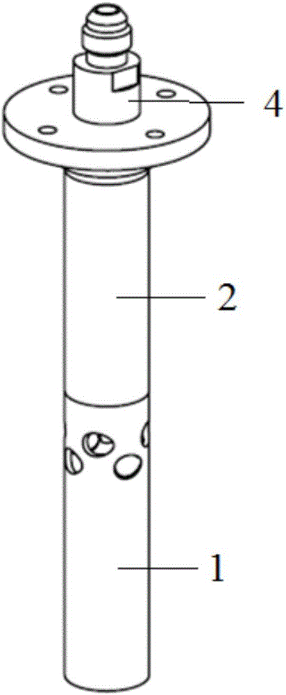
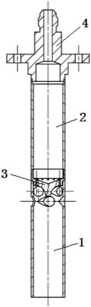
[0043] like figure 1 and figure 2 As shown, this embodiment includes: a mixing tube 1, a biogas tube 2, a gas fitting 3 and a connecting accessory 4, wherein: the top of the mixing tube 1 is welded to the bottom of the biogas tube 2, and the top of the biogas tube 2 is welded to the bottom of the connecting accessory 4 , The gas distribution part 3 is installed between the mixing pipe 1 and the biogas pipe 2.
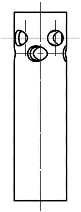
[0044] The structure of the mixing tube 1 is as image 3 As shown, its length is 4 times of the outer diameter of the mixing tube, and its thickness is 0.06 times of the outer diameter; there are two rows of 8 air holes on it, and the hole diameter is 0.25 times of the outer diameter; each row of two adjacent air holes The angle between the axes is 90°, and the distance between the axis and the axis of the mixing tube is 0.29 times the outer diameter; the angle between the axes of two adjacent air holes in the upper and lower rows is 45°, and the distance between the...
Embodiment 2
[0055] A biogas swirl premixing nozzle device, including a mixing tube, a biogas tube, an air distribution piece and connecting accessories. The mixing tube is located below the nozzle, and 6 air holes are opened on the upper part, the top is welded to the bottom of the biogas pipe, and the gas distribution piece is opened There are 8 biogas holes, which are installed between the mixing pipe and the biogas pipe. The connecting accessories are located at the top and welded to the top of the biogas pipe.
[0056] Next, we will further explain the composition of each component: the air holes are divided into upper and lower rows, each row has 3 air holes, and the angle between the axes of two adjacent air holes in each row is 120°; The angle between the axis of each air hole is 60°. The axis of the air hole is perpendicular to the axis of the mixing tube to ensure that the air hole is tangent to the inner wall of the mixing tube, the distance between the axes is 0.04d, and the di...
Embodiment 3
[0058] A biogas swirl premixing nozzle device, including a mixing tube, a biogas tube, gas distribution parts and connecting accessories, the mixing tube is located below the nozzle, and 12 air holes are opened on the upper part, the top is welded to the bottom of the biogas tube, and the gas distribution part is opened There are 16 biogas holes, which are installed between the mixing pipe and the biogas pipe. The connecting accessories are located at the top and welded to the top of the biogas pipe.
[0059] Next, we will further explain the composition of each component: the air holes are divided into upper and lower rows, each row has 6 air holes, and the angle between the axes of two adjacent air holes in each row is 60°; The angle between the axis of each air hole is 30°. The axis of the air hole is perpendicular to the axis of the mixing tube to ensure that the air hole is tangent to the inner wall of the mixing tube, the distance between the axes is 0.29d, and the diame...
PUM
 Abstract
Description
Claims
Application Information
 - Generate Ideas
- Intellectual Property
- Life Sciences
- Materials
- Tech Scout
- Unparalleled Data Quality
- Higher Quality Content
- 60% Fewer Hallucinations
Browse by: Latest US Patents, China's latest patents, Technical Efficacy Thesaurus, Application Domain, Technology Topic, Popular Technical Reports.
© 2025 PatSnap. All rights reserved.Legal|Privacy policy|Modern Slavery Act Transparency Statement|Sitemap|About US| Contact US: help@patsnap.com