Metallized thin film dividing and cutting machine

A metallized film, slitting machine technology, applied in metal processing and other directions, can solve the problems of flexibility, lack of multi-angle convenience, cutter head offset, poor stability, etc., to achieve the effect of flexibility

Active Publication Date: 2017-03-29
TONGLING QILI ELECTRONICS MATERIALS
View PDF9 Cites 7 Cited by
  • Summary
  • Abstract
  • Description
  • Claims
  • Application Information

AI Technical Summary

Problems solved by technology

[0004] (1) The knife head positioning device in the slitting mechanism is mostly like the structure of the knife head positioning device disclosed in the film slitting machine disclosed in the patent application 201420418295.X, specifically a film roll with cutting grooves. The knife head of this structure The positioning device makes the film width after slitting only a multiple of the width of the cutting groove, and the slitting of other width films cannot be realized; in addition, the film roll is a cylindrical structure, and the film passes between the film roll and the knife head. The stability of transmission and cutting is poor
[0005] (2) During the actual slitting, according to the different parameters such as film thickness and hardness, it is necessary to adjust the inclination angle of the slitting knife. The traditional method of adjusting the inclination angle of the slitting knife is disclosed in the patent application 201120303631.2 film slitting machine In order to realize the adjustment of the inclination angle of th...

Method used


Image

  • Metallized thin film dividing and cutting machine
  • Metallized thin film dividing and cutting machine
  • Metallized thin film dividing and cutting machine

Examples


Embodiment Construction

[0045] In order to further describe the present invention, it is further described below in conjunction with embodiment.

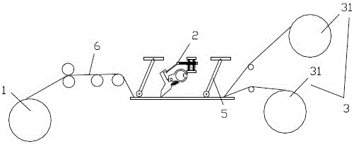
[0046] Such as figure 1 As shown, the present invention discloses a metallized film slitting machine, which includes a feeding mechanism 1 , a slitting mechanism 2 , and a film rolling mechanism 3 . The feeding mechanism 1, the cutting mechanism 2, and the film rolling mechanism 3 are sequentially arranged on the frame according to the technological process from front to back. In the present invention, guide rollers and tension rollers are also arranged on the frame, and in some embodiments, traction pair rollers are also arranged. The transmission power of the film 6 of the present invention is preferably driven by the film rolling mechanism 3 . The feeding mechanism 1 of the present invention is a film feeding mechanism of the prior art.

[0047] The present invention rotates through the film rolling mechanism 3, pulls the film 6 to transmit, realizes...


PUM


Abstract

The invention discloses a metallized thin film dividing and cutting machine, which comprises a feeding mechanism, a dividing and cutting mechanism and a film winding mechanism. The feeding mechanism, the dividing and cutting mechanism and the film winding mechanism are sequentially arranged from front to back according to a technological process; the dividing and cutting mechanism comprises a dividing and cutting cutter assembly and a movable positioning mechanism; a thin film is transferred between the dividing and cutting cutter assembly and the movable positioning mechanism; film pressing mechanisms are arranged between the feeding mechanism and the dividing and cutting mechanism as well as between the dividing and cutting mechanism and the film winding mechanism respectively; each film pressing mechanism comprises a rocking bar; the upper ends of the rocking bars are hinged to a rack; the lower ends of the rocking bars extend to positions above adjusting plates and can make contact with the thin film; the film winding mechanism comprises a film winding shaft and multiple groups of film winding barrels; the outer diameters of the multiple groups of film winding barrels are different; and any two film winding barrels can be in screw-thread fit. The metallized thin film dividing and cutting machine provided by the invention has the advantages of convenience in operation, capability of effectively preventing relative sliding between cutting heads and shafts, adjustment flexibility and diversity in thin film dividing and cutting breadth, and precision in rotation angles of dividing and cutting cutters.

Description

technical field [0001] The invention relates to the technical field of metallized films, in particular to a metallized film slitting machine. Background technique [0002] The metallized film slitting machine is a device that cuts the metallized film processed by the vacuum coating machine according to the width requirement. It includes a feeding mechanism, a cutting mechanism, and a film rolling mechanism. The feeding mechanism is used to feed the metallized film to be cut, the slitting mechanism is used to cut the fed metallized film, and the film rolling mechanism is used to The slit metallized film is wound. [0003] At present, the existing metallized film slitting machine has the following deficiencies: [0004] (1) The knife head positioning device in the slitting mechanism is mostly like the structure of the knife head positioning device disclosed in the film slitting machine disclosed in the patent application 201420418295.X, specifically a film roll with cutting ...

Claims


Application Information

Patent Timeline
IPC IPC(8): B26D1/30B26D7/26B26D7/08B26D7/00
CPCB26D1/305B26D7/00B26D7/08B26D7/2628
Inventor 荚朝辉康仙文
Owner TONGLING QILI ELECTRONICS MATERIALS
Why Eureka
Try Eureka