Mobile terminal heat radiation structure and mobile terminal

A mobile terminal and heat dissipation structure technology, applied in the field of communications, can solve the problems of slow air flow, low natural convection heat dissipation efficiency, and unsatisfactory heat dissipation effect, and achieve the effect of improving heat dissipation efficiency and heat dissipation.

Inactive Publication Date: 2017-03-22
NUBIA TECHNOLOGY CO LTD
View PDF9 Cites 4 Cited by
  • Summary
  • Abstract
  • Description
  • Claims
  • Application Information

AI Technical Summary

Problems solved by technology

[0003] The heat dissipation method of smart electronic products currently used is mainly heat dissipation materials such as graphite and copper foil. Due to the dense internal components of smart electronic products and the slow air flow, it is difficult to quickly dissipate heat to the outside air in this way; Some high-end smart electronic products use heat pipes and other heat dissipation methods to dissipate heat. This measure mainly dissipates heat by natural convection. However, the heat dissipation efficiency of natural convection is relatively low, and the heat dissipation effect is not ideal.

Method used


Image

  • Mobile terminal heat radiation structure and mobile terminal
  • Mobile terminal heat radiation structure and mobile terminal

Examples


Embodiment Construction

[0027] It should be understood that the specific embodiments described here are only used to explain the present invention, not to limit the present invention.

[0028] A mobile terminal implementing various embodiments of the present invention will now be described with reference to the accompanying drawings. In the following description, use of suffixes such as 'module', 'part' or 'unit' for denoting elements is only for facilitating description of the present invention and has no specific meaning by itself. Therefore, "module" and "component" may be used mixedly.

[0029] Mobile terminals may be implemented in various forms. For example, terminals described in the present invention may include devices such as mobile phones, smart phones, notebook computers, digital broadcast receivers, PDAs (Personal Digital Assistants), PADs (Tablet Computers), PMPs (Portable Multimedia Players), navigation devices, etc. mobile terminals and fixed terminals such as digital TVs, desktop c...


PUM


Abstract

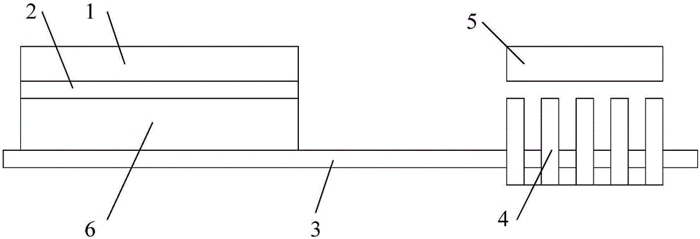
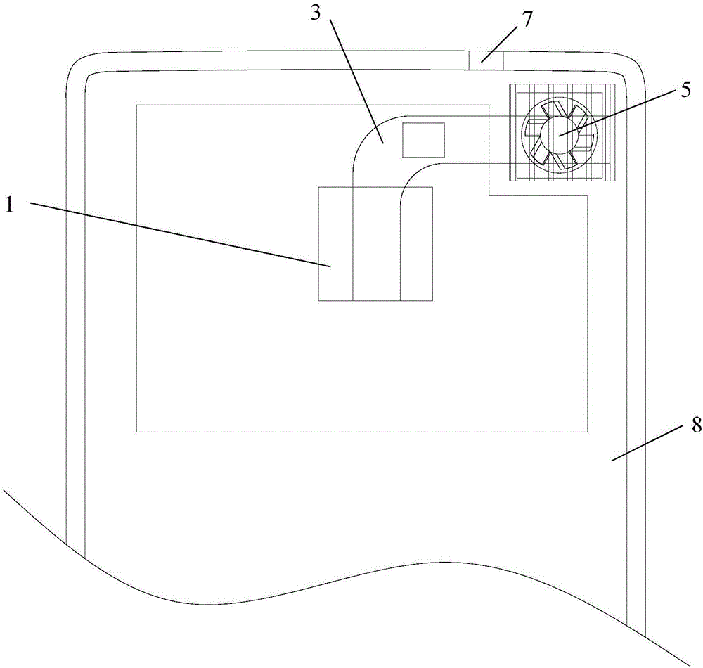
The invention discloses a mobile terminal heat radiation structure and a mobile terminal. The mobile terminal heat radiation structure comprises a heating member, a heat conduction member connected with the heating member, a heat radiation member contacting with the heat conduction member, a fan which is arranged in a mode of corresponding to the heat radiation member and is used for carrying out heat radiation for the heat radiation member, and a control unit electrically connected with the fan, wherein heat of the heating member is conducted through the heat conduction member to the heat radiation member. The heat radiation structure is advantaged in that heat of the heating member can be rapidly radiated, a purpose of improving heat radiation efficiency of the heating member is realized, and thereby heat radiation requirements of large-scale 3D games and high definition videos during applications for the heating member can be satisfied.

Description

technical field [0001] The invention relates to communication technology, in particular to a heat dissipation structure of a mobile terminal and a mobile terminal. Background technique [0002] With the development of smart electronic products, the number of CPU cores is increasing, which better satisfies users' pursuit of large-scale 3D games and high-definition videos. The heat generated by the product is getting bigger and bigger. After the heat is dissipated and acts on the shell of the smart electronic product, it will affect the customer's experience of using the smart electronic product; especially after the popularity of the all-metal body, the heat generated is more likely to spread to the all-metal machine. On the body, consumers are more sensitive to the surface temperature of smart electronic products. [0003] The heat dissipation method of smart electronic products currently used is mainly heat dissipation materials such as graphite and copper foil. Due to the...

Claims


Application Information

Patent Timeline
IPC IPC(8): H05K7/20
CPCH05K7/20136H05K7/20209H05K7/2039
Inventor 龙静赵军宏罗孝平
Owner NUBIA TECHNOLOGY CO LTD
Why Eureka
Try Eureka