
Method and device for position sensorless control of permanent magnet synchronous motor

A technology of permanent magnet synchronous motor and control method, which is applied in the direction of motor control, motor generator control, control of electromechanical transmission, etc., and can solve the problems of difficult to obtain high-precision rotor position and speed information, poor accuracy, etc.

Active Publication Date: 2017-03-22
SUNGROW POWER SUPPLY CO LTD
View PDF6 Cites 22 Cited by
  • Summary
  • Abstract
  • Description
  • Claims
  • Application Information

AI Technical Summary

Problems solved by technology

At present, relatively mature algorithms include the direct calculation method of back electromotive force, the high-frequency signal injection method, and the observer method, etc., but these algorithms all have the same defect, that is, the accuracy is poor in the zero-speed and low-speed sections, so it is difficult to operate in the full speed range. Both obtain high-precision rotor position and speed information

Method used


Image

  • Method and device for position sensorless control of permanent magnet synchronous motor
  • Method and device for position sensorless control of permanent magnet synchronous motor
  • Method and device for position sensorless control of permanent magnet synchronous motor

Examples


Embodiment Construction

[0049] The following will clearly and completely describe the technical solutions in the embodiments of the present invention with reference to the accompanying drawings in the embodiments of the present invention. Obviously, the described embodiments are only some, not all, embodiments of the present invention. Based on the embodiments of the present invention, all other embodiments obtained by persons of ordinary skill in the art without making creative efforts belong to the protection scope of the present invention.

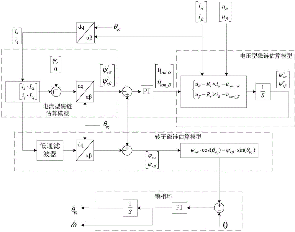
[0050] see figure 1 , the embodiment of the present invention discloses a position sensorless control method for a permanent magnet synchronous motor to achieve high-precision rotor position and speed information in the full speed range, including:

[0051] Step S01: Determine the current-type stator flux linkage in the d-q coordinate system (ie, the two-phase synchronously rotating coordinate system).

[0052] Specifically, the determining the current-type s...


PUM


Abstract

The invention discloses a method and a device for position sensorless control of a permanent magnet synchronous motor. The method comprises the following steps: determining a current-mode stator flux linkage under a d-q coordinate system, then using a rotor position estimated last time as positional information to carry out reversed Park conversion on the current-mode stator flux linkage so as to obtain a current-mode stator flux linkage under an alpha-beta coordinate system; using a voltage-mode stator flux linkage in which a model deviation compensation controlled quantity is introduced to estimate a voltage-mode stator flux linkage under the alpha-beta coordinate system, wherein the compensation controlled quantity is output quantity, after regulated by a regulator, of deviation between the current-mode stator flux linkage and the voltage-mode stator flux linkage estimated last time; obtaining a rotor flux linkage under the d-q coordinate system according to the voltage-mode stator flux linkage; and using a phase-locked loop to lock the q-axis component of the rotor flux linkage to be zero, and estimating the rotor position and velocity information of the permanent magnet synchronous motor, so that high-precision rotor position and velocity information can be obtained in a full range of speed.

Description

technical field [0001] The invention relates to the technical field of motor control, and more specifically, to a position sensorless control method and device for a permanent magnet synchronous motor. Background technique [0002] The permanent magnet synchronous motor speed control system needs to obtain accurate rotor position and speed information as feedback to form a closed-loop control. However, using a high-precision position sensor to directly measure the rotor position and speed information not only increases the system cost, but also reduces the system stability. In order to overcome the above shortcomings of the position sensor, the position sensorless control technology of permanent magnet synchronous motor came into being. [0003] The position sensorless control technology of permanent magnet synchronous motor refers to the technology of using appropriate algorithm to estimate the rotor position and speed information, thereby replacing the position sensor. A...

Claims


Application Information

Patent Timeline
IPC IPC(8): H02P21/00H02P21/28H02P21/18
CPCH02P21/0017H02P2203/01
Inventor 于安博杨晗顾亦磊
Owner SUNGROW POWER SUPPLY CO LTD
Learn More