Online gas collecting and exhausting device and method for nuclear power station fluid system non-condensable gas

A fluid system and exhaust device technology, applied in the field of nuclear power, can solve the problems of large discharge fluid, flow field cavitation, high discharge flow, etc., and achieve the effects of avoiding a large amount of discharge, wide application range and simple structure

Inactive Publication Date: 2017-03-22
中广核工程有限公司 +1
View PDF6 Cites 0 Cited by
  • Summary
  • Abstract
  • Description
  • Claims
  • Application Information

AI Technical Summary

Problems solved by technology

However, there are some disadvantages in the above exhaust method: 1) It is not suitable for systems with higher pressure. When the pressure is significantly higher than atmospheric pressure, such as exceeding 1MPa, the pressure at the exhaust point will drop rapidly when the exhaust valve is opened, which may cause Local cavitation in the flow field, and the discharge flow rate is too high; 2) It is not suitable for systems that need to control the discharge of radioactive fluids, which may cause excessive discharge of fluids and high cost of radioactive waste management

Method used


Image

  • Online gas collecting and exhausting device and method for nuclear power station fluid system non-condensable gas
  • Online gas collecting and exhausting device and method for nuclear power station fluid system non-condensable gas

Examples


Embodiment 1

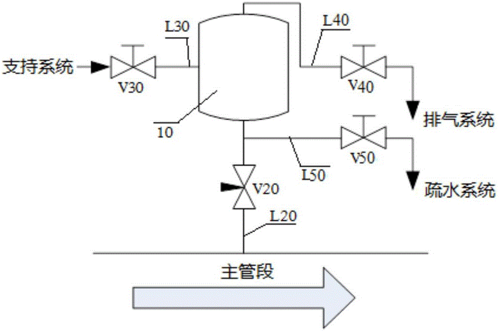
[0037] Please refer to figure 2 As shown, the noncondensable gas online gas collection and exhaust device of the nuclear power plant fluid system of the present invention includes: a gas collection tank 10, a gas collection pipeline L20 connected to the bottom of the gas collection tank 10, a gas collection valve V20, and a water injection valve connected to the gas collection tank 10 V30 and water injection pipeline L30, exhaust pipeline L40 and exhaust valve V40 connected to the top of the gas collection tank 10, and drain pipeline L50 and drain valve V50 connected to the gas collection pipeline L20. The local high point of the segment fluid system is connected, and the drain line L50 is connected to the gas collection line L20 between the gas collection tank 10 and the gas collection valve V20.

[0038] The gas collection valve V20 is installed vertically on the gas collection pipeline L20 and above the main section of the nuclear power plant, and the gas collection tank 1...

Embodiment 2

[0046] For the exhaust work of the high temperature and high pressure fluid system in nuclear power plants, please refer to figure 2 As shown, its structure is basically the same as the structure of Embodiment 1 of the non-condensable gas online gas collection and exhaust device of the nuclear power plant fluid system of the present invention, the difference is only that the support system (not shown), the hydrophobic exhaust system (not shown) Shown) and the cooling device of the air collecting tank 10.

[0047] According to Embodiment 2 of the present invention, for the high-temperature and high-pressure system, in the exhaust stage, it is first necessary to properly cool down the gas collecting tank 10, and the cooling can be through natural heat dissipation, or a forced convection cooling device can be added externally; secondly, it needs to be upstream of the water injection valve V30 Set pressurization measures (such as plunger pumps) to increase the injected fluid to t...

Embodiment 3

[0051] For the special environment where the radioactive intensity is high in nuclear power plants, or the installation position of the main pipe section is high, and it is difficult for operators to approach, the structure of Embodiment 3 of the present invention is the same as that of Embodiment 1 of the noncondensable gas online gas collection and exhaust device for the fluid system of a nuclear power plant of the present invention. The structures are basically the same, the only difference is that the water injection valve V30, the exhaust valve V40 and the steam trap V50 are installed in relatively far away from the gas collection tank 10 and are easily accessible. The gas collecting valve V20 is preferably a solenoid valve, and may also be an electric valve or a pneumatic valve, which is convenient for the operator to operate safely. The gas collection process and exhaust process in Embodiment 3 of the present invention are consistent with the gas collection process and e...


PUM


Abstract

The invention discloses an online gas collecting and exhausting device for nuclear power station fluid system non-condensable gas. The online gas collecting and exhausting device comprises a gas collecting tank, a gas collecting pipeline, a gas collecting valve, a water injection valve, a water injection pipeline, a gas exhausting pipeline, an exhaust valve, a hydrophobic pipeline and a hydrophobic valve, wherein the gas collecting pipeline and the gas collecting valve are connected to the bottom of the gas collecting tank, the water injection valve and the water injection pipeline are connected to the gas collecting tank from upstream, the gas exhausting pipeline and the exhaust valve are connected to the top of the gas collecting tank, and the hydrophobic pipeline and the hydrophobic valve are connected to the gas collecting pipeline. In addition, the invention further discloses an online gas collecting and exhausting method for the nuclear power station fluid system non-condensable gas. Compared with the prior art, the online gas collecting and exhausting device for the nuclear power station fluid system non-condensable gas has the advantages of being simple in structure, convenient to operate, suitable for nuclear power station fluid systems different in pressure and fluid, and capable of effectively avoiding system outage and radioactive fluid leakage.

Description

technical field [0001] The invention belongs to the technical field of nuclear power. More specifically, the invention relates to an online gas collection and exhaust device and method for noncondensable gas in a fluid system of a nuclear power plant. Background technique [0002] During the operation of a nuclear power plant, the non-condensable gas in the fluid system of the nuclear power plant has many hazards to the operation of the system: for example, the operation of the pump is unstable or even fails, the local flow field is blocked, and the pressure boundary of the system is destroyed due to the formation of transient flow. In addition, non-condensable gases in nuclear power plant fluid systems can cause undesired spread of radioactive material if not handled properly. [0003] Since a considerable part of the fluid system in the nuclear power plant makes an important contribution to the safety and normal operation of the nuclear power plant and is managed by the op...

Claims


Application Information

Patent Timeline
Patent Type & Authority Applications(China)
IPC IPC(8): G21C15/16G21C15/253
CPCG21C15/16G21C15/253Y02E30/30
Inventor 杨廷胡剑彭跃
Owner 中广核工程有限公司
Why Eureka
Try Eureka