Target image-based mechanical rotation eliminating mechanism

A target image and mechanical technology, applied in optical components, optics, instruments, etc., can solve the problems of difficult optical path imaging, lengthened optical path, increased volume, etc., and achieve the effect of simple axis arrangement and improved stability.

Active Publication Date: 2017-03-22
LUOYANG INST OF ELECTRO OPTICAL EQUIP OF AVIC
View PDF6 Cites 0 Cited by
  • Summary
  • Abstract
  • Description
  • Claims
  • Application Information

AI Technical Summary

Problems solved by technology

Optical derotation is to install a derotation prism in front of the imaging unit along the optical axis of the imaging unit in the optical path of the system, and rely on the rotation of the derotation prism to realize the rotation of the target image, thereby eliminating the rotation of the target image. This processing method The Dove prism can only be used in the visible light to near-infrared band due to the limitation of optical materials, while the derotation of the K mirror has the problems of lengthening the optical path of the system, increasing the volume, and making it difficult to image the optical path in a small instantaneous field of view.

Method used


Image

  • Target image-based mechanical rotation eliminating mechanism
  • Target image-based mechanical rotation eliminating mechanism
  • Target image-based mechanical rotation eliminating mechanism

Examples


Embodiment Construction

[0029] Now in conjunction with embodiment, accompanying drawing, the present invention will be further described:

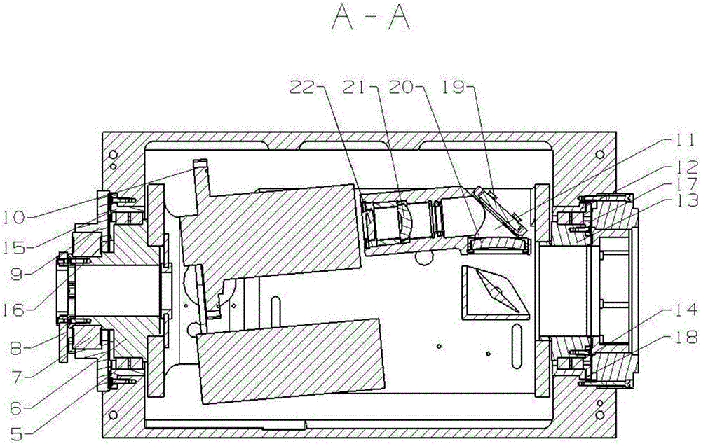
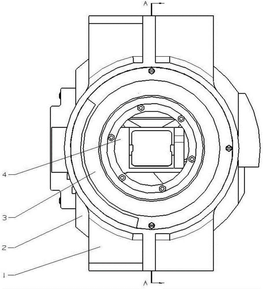
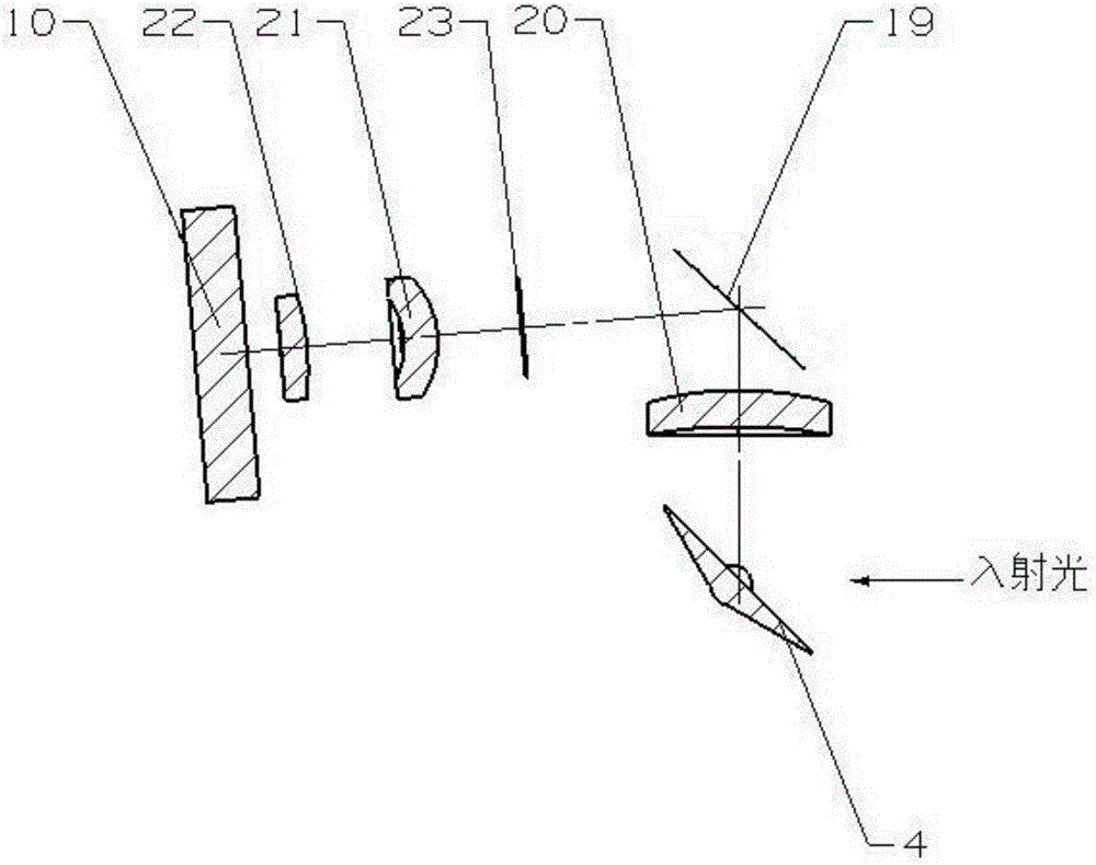
[0030] image 3 It is a schematic diagram of an optical imaging system adopted by a mechanical derotation mechanism based on an object image in the present invention. The optical system is sequentially provided with an oscillating mirror unit 4 , a first lens 20 , a fixed mirror 19 , a diaphragm 23 , a second lens 21 , a third lens 22 and an imaging unit 10 along the optical axis. The first lens 20 , the fixed mirror 19 , the second lens 21 and the third lens 22 constitute the converging unit 11 of the system. The above-mentioned optical devices are installed on the inner frame 2, and under the control of the mechanical derotation mechanism of the present invention, the imaging unit can be rotated around the axis of the incident light, thereby eliminating the rotation of the target image.

[0031] The radius of the first surface of the third lens 22 in the conv...


PUM


Abstract

The present invention relates to a target image-based mechanical rotation eliminating mechanism. The target image-based mechanical rotation eliminating mechanism comprises a shaft system adopting an inner frame as a main body and a part adopting an outer frame as a main body; a torque motor is controlled through the induction signals of a rotation changing unit; the rotation motion of the torque motor is converted into the rotation motion of the shaft system; and a swing mirror unit, an imaging unit and a converging unit which are all arranged in the inner frame rotate according to a certain angle, so that the mechanical rotation elimination of a target image is achieved. According to the technical schemes of the invention, the torque motor directly drives the imaging unit to rotate around the axis of an optical system, so that dynamic performance is excellent. Based on the design of the matching parameters of the units, the rotation of the target image can be eliminated; the arrangement of the shaft system is relatively simple; a small number of optical lenses are adopted; and the target image can be dynamically controlled in real time, and therefore, the stability of the target image can be improved. The target image-based mechanical rotation eliminating mechanism can be applied to an infrared optical system requiring rotation elimination.

Description

technical field [0001] The invention belongs to the mechanical derotation technology of images, and in particular relates to a mechanical derotation mechanism based on target images. Background technique [0002] The airborne infrared photoelectric detection system is an important part of the aircraft weapon fire control system. The airborne photoelectric detection system uses infrared passive detection and tracking to realize all-weather detection, tracking and targeting of air, ground and water targets. It has radio silence and anti-electromagnetic interference. Strong capability and high target resolution. In the airborne infrared photoelectric detection system, the gyro platform is generally used to isolate the vibration of the carrier aircraft, and the precession characteristics of the platform are used to complete the tracking of the target. During the stabilization and tracking process of the system, the rotation of the platform frame causes the movement of the optic...

Claims


Application Information

Patent Timeline
Patent Type & Authority Applications(China)
IPC IPC(8): G02B26/08
CPCG02B26/08
Inventor 张杰张鹏张磊牛双傅家
Owner LUOYANG INST OF ELECTRO OPTICAL EQUIP OF AVIC
Why Eureka
Try Eureka