Heat accumulating type intelligent warm air blower
A heater and regenerative technology, which is applied in the field of regenerative smart heaters to achieve the effect of simple structure and easy promotion
- Summary
- Abstract
- Description
- Claims
- Application Information
AI Technical Summary
Problems solved by technology
Method used
Image


Examples
Embodiment 1
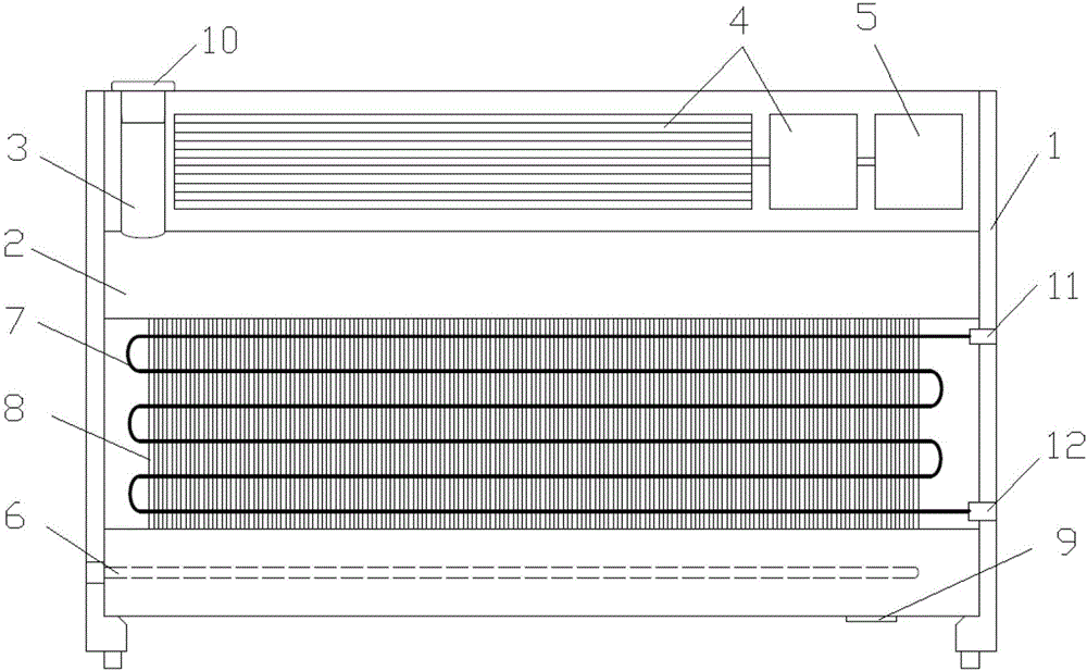
[0030] Such as figure 1 and figure 2 As shown, the thermal storage type intelligent heater provided in the first embodiment includes a housing 1, an air outlet 13 and an air inlet 14 located on the housing 1, and an air outlet 14 placed in the housing 1 and connected to the outlet. The cross-flow fan 4 communicated with the tuyere 13 also includes a heat accumulator 2 arranged in the housing 1; there is an air flow layer between the heat accumulator 2 and the housing 1 .
[0031] Wherein, the heat accumulator 2 is provided with an electric heater 6 , a water inlet 3 and a water outlet 9 . The electric heater 6 heats the medium in the heat accumulator 2 after being energized, and the medium may be water or a phase change heat storage material. The water inlet 3 is located at the top of the heat accumulator 2 and directly communicates with the heat accumulator 2 , water can be added to the heat accumulator 2 through the water inlet 3 . The drain port 9 is located at the bot...
Embodiment 2
[0037] Such as figure 1 and figure 2 As shown, the thermal storage type intelligent heater provided in the first embodiment includes a housing 1, an air outlet 13 and an air inlet 14 located on the housing 1, and an air outlet 14 placed in the housing 1 and connected to the outlet. The cross-flow fan 4 communicated with the tuyere 13 also includes a heat accumulator 2 arranged in the housing 1; there is an air flow layer between the heat accumulator 2 and the housing 1 .
[0038] Wherein, the heat accumulator 2 is provided with an electric heater 6 , a water inlet 3 and a water outlet 9 . The electric heater 6 heats the medium in the heat accumulator 2 after being energized, and the medium may be water or a phase change heat storage material. The water inlet 3 is located at the top of the heat accumulator 2 and directly communicates with the heat accumulator 2 , water can be added to the heat accumulator 2 through the water inlet 3 . The drain port 9 is located at the bot...
Embodiment 3
[0047] Such as figure 1 and figure 2 As shown, the thermal storage type intelligent heater provided in the first embodiment includes a housing 1, an air outlet 13 and an air inlet 14 located on the housing 1, and an air outlet 14 placed in the housing 1 and connected to the outlet. The cross-flow fan 4 communicated with the tuyere 13 also includes a heat accumulator 2 arranged in the housing 1; there is an air flow layer between the heat accumulator 2 and the housing 1 .
[0048] Wherein, the heat accumulator 2 is provided with an electric heater 6 , a water inlet 3 and a water outlet 9 . The electric heater 6 heats the medium in the heat accumulator 2 after being energized, and the medium may be water or a phase change heat storage material. The water inlet 3 is located at the top of the heat accumulator 2 and directly communicates with the heat accumulator 2 , water can be added to the heat accumulator 2 through the water inlet 3 . The drain port 9 is located at the bot...
PUM
 Abstract
Description
Claims
Application Information
 - Generate Ideas
- Intellectual Property
- Life Sciences
- Materials
- Tech Scout
- Unparalleled Data Quality
- Higher Quality Content
- 60% Fewer Hallucinations
Browse by: Latest US Patents, China's latest patents, Technical Efficacy Thesaurus, Application Domain, Technology Topic, Popular Technical Reports.
© 2025 PatSnap. All rights reserved.Legal|Privacy policy|Modern Slavery Act Transparency Statement|Sitemap|About US| Contact US: help@patsnap.com