
Casing oil recovery device and process

A technology of oil recovery and casing, which is applied in the direction of production fluid, wellbore/well components, earthwork drilling and production, etc. It can solve the problems of no casing oil recovery technology and application device, unfavorable refined management, and less recovered liquid. , to achieve the effects of scientific management, prevention of oil stealing, and accurate measurement

Inactive Publication Date: 2018-08-24
河北众杰石油设备修理有限公司
View PDF9 Cites 0 Cited by
  • Summary
  • Abstract
  • Description
  • Claims
  • Application Information

AI Technical Summary

Problems solved by technology

[0002] At present, the collection and recovery of the liquid in the oil and casing annulus is usually carried out by manual regular or irregular inspection of the liquid in the oil and casing annulus, and the recovery of the liquid in the oil and casing annulus is carried out by recovery tankers. The artificial method does not take recovery measures based on the pressure or liquid level of the liquid in the well. If the recovery is late, the liquid will overflow and cause environmental pollution. less
Although this method is simple, it is not conducive to fine management
It is also easy to cause the occurrence of oil theft incidents
[0003] At present, there is no relevant casing oil recovery technology and application device

Method used


Image

  • Casing oil recovery device and process
  • Casing oil recovery device and process
  • Casing oil recovery device and process

Examples


Embodiment Construction

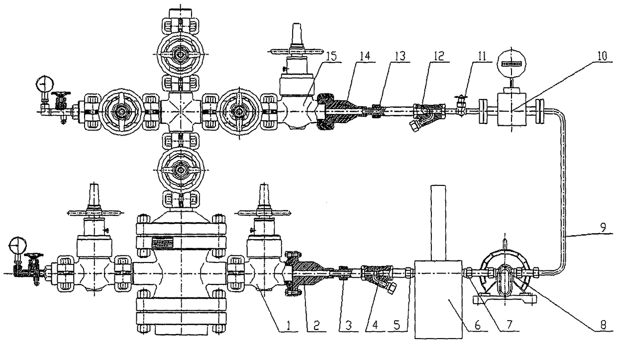
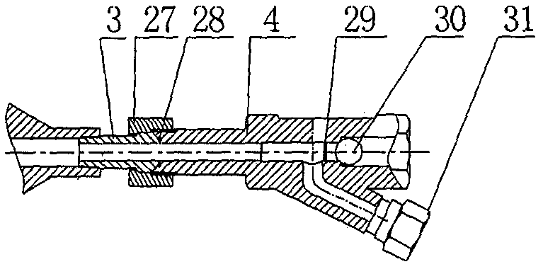
[0029] A casing oil recovery device, comprising a liquid inlet valve 1 connected to the valve of the oil production well, characterized in that: the liquid inlet valve 1 is connected to the short connection A2 through a clamp or a flange, and the oil valve is connected One end of A3 is connected with the connecting short-circuit A2 screw, and the other end of connecting oil nonel A3 is in contact with filter check valve A4. It can be rotated arbitrarily within the range of ±30°, and is threadedly connected with the filter check valve A4 through the nut 27; the liquid inlet 5 of the data collector 6 is connected with the filter check valve A4, and the liquid outlet 7 is connected with the recovery pump 8 connection, the recovery pump 8 is connected to the filter check valve B12 through the pipeline 9, the flow meter 10 and the stop valve 11 are installed on the pipeline 9, the end of the connection oil nonel B13 is connected with the short connection B14 screw, and the oil nonel...


PUM


Abstract

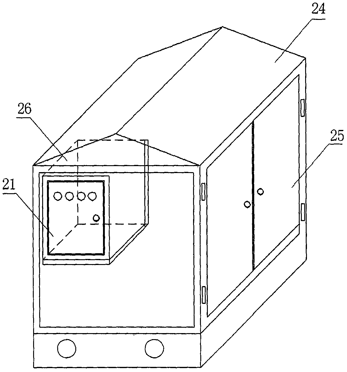
The invention provides a device and technique for recovering oil in a casing pipe. The device for recovering oil in the casing pipe comprises a liquid inlet valve connected with a producing well valve. The device is characterized in that the liquid inlet valve is connected with a connecting pup joint A, one end of a connecting union A is connected with the connecting pup joint A, and the other end of the connecting union A makes contact with a filter one-way valve A and is locked and fixed through a nut; a liquid inlet of a data collector is connected with the filter one-way valve A, and a liquid outlet of the data collector is connected with a recovery pump; the recovery pump is connected with a filter one-way valve B through a pipeline, and a flow meter and a stop valve are mounted on the pipeline; one end of a connecting union B is connected with a connecting pup joint B, and the other end of the connecting union B makes contact with the filter one-way valve B and is locked and fixed through a nut; and the connecting pup joint B is connected with a liquid outlet valve, and the liquid outlet valve is connected with a main producing pipeline. By adoption of the device and technique for recovering oil in the casing pipe, oil and the pressure or liquid level in the annulus of the casing pipe do not need to be manually checked specially, liquid overflow caused by delayed checking or human factors is avoided, and the labor intensity of workers is relieved; and an anti-theft box is used for comprehensive protection, and thus oil can be effectively prevented from being stolen.

Description

technical field [0001] The invention relates to the technical field of oil and gas exploitation, in particular to a casing oil recovery device and process. Background technique [0002] At present, the collection and recovery of the liquid in the oil and casing annulus is usually carried out by manual regular or irregular inspection of the liquid in the oil and casing annulus, and the recovery of the liquid in the oil and casing annulus is carried out by recovery tankers. The artificial method does not take recovery measures based on the pressure or liquid level of the liquid in the well. If the recovery is late, the liquid will overflow and cause environmental pollution. less. Although this method is simple, it is not conducive to fine management. It is also easy to cause the occurrence of oil theft incidents. [0003] At present, there is no relevant casing oil recovery technology and application device. Contents of the invention [0004] In view of the deficiencies ...

Claims


Application Information

Patent Timeline
Patent Type & Authority Patents(China)
IPC IPC(8): E21B43/00
CPCE21B43/00
Inventor 张建伟刘涛董惠娟
Owner 河北众杰石油设备修理有限公司
Learn More