
An anchorage structure for steel pipe pile bottom in bare rock geological force

A steel pipe pile and geology technology, applied in sheet pile wall, foundation structure engineering, construction, etc., can solve the problems of small actual pile end bearing capacity, pile bottom concrete damage, difficult control of spacing and height, etc.

Active Publication Date: 2018-12-18
ROAD & BRIDGE EAST CHINA ENG +1
View PDF7 Cites 0 Cited by
  • Summary
  • Abstract
  • Description
  • Claims
  • Application Information

AI Technical Summary

Problems solved by technology

[0009] ② Steel pipe piles and concrete only produce binding force on the inner side, and the material properties are not fully developed
[0013] ①It is difficult to control the distance and height of the notches at the bottom of the steel pipe piles, resulting in a waste of steel pipe pile materials, and after opening the notches, the steel pipe piles’ stressed section is weakened
[0014] ②Although the steel pipe pile and the concrete exert a gripping force on both sides, the shear effect of the pile tip on the concrete is easy to damage the concrete at the bottom of the pile, resulting in the actual bearing capacity of the pile tip being less than the calculated value, and uneven settlement at the pile tip

Method used


Image

  • An anchorage structure for steel pipe pile bottom in bare rock geological force
  • An anchorage structure for steel pipe pile bottom in bare rock geological force

Examples


Embodiment Construction

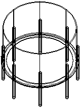
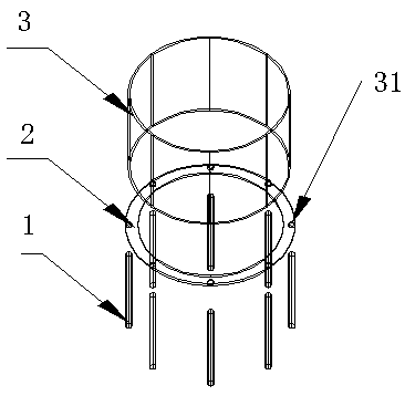
[0033] See figure 1 , 2 , The present invention discloses an anchoring structure at the bottom of a steel pipe pile under bare rock geology, which includes the following steps:

[0034] A. Processing supporting steel bars 1;

[0035] B. Processing 2 pieces of annular support steel plate;

[0036] C. Prepare 3 steel pipe pile protection tube or one steel pipe pile;

[0037] D. Weld the annular support steel plate 2 with the steel pipe pile protective tube 3 or the bottom of the steel pipe pile into a whole, and set the steel pipe pile into the steel pipe pile protective tube 3 and set it in the middle position of the annular support steel plate 2, or the steel pipe pile The bottom is set at the middle position of the annular support steel plate 2;

[0038] E. Weld the supporting steel bars 1 in turn around the annular supporting steel plate 2;

[0039] F. After the hole formation of the bedrock is completed, the steel pipe pile is hoisted into the hole, and underwater concrete is poured ...


PUM


Abstract

The invention relates to an anchoring structure for the pile bottom of steel pipe piles under bare rock geological force. The steps are: A, processing the foot reinforcement; B, processing the annular supporting steel plate; C, preparing the steel pipe pile casing or steel pipe pile; D, welding the annular supporting steel plate and the steel pipe pile casing or the bottom of the steel pipe pile into a whole , the steel pipe piles are inserted into the steel pipe pile casing and set in the middle of the circular support steel plate, or the steel pipe piles are set in the middle of the circular support steel plate; E, weld the leg steel bars around the circular support steel plate in sequence; F, after the bedrock hole is completed , hanging steel pipe piles into the holes, and pouring underwater concrete to form a stable stress-bearing structure. During the construction of stressed steel pipe piles, by adding ribbed steel support feet at the bottom of the steel pipe piles, the concrete inside the steel pipes can smoothly pass through the gap at the bottom of the piles, and turn out to be between the steel pipes and the hole wall, and the gap between the concrete and the steel pipe piles The holding force of the pile is doubled; the welding of the ring-shaped steel plate support pad and the bottom of the steel pipe pile is avoided, the shear effect between the pile bottom and the concrete is avoided, the anchoring effect of the concrete pile bottom is fully exerted, and the force of the steel pipe pile is ensured. performance.

Description

Technical field [0001] The invention relates to a construction structure of a steel pipe pile foundation, in particular to an anchoring structure at the bottom of a steel pipe pile under bare rock geology. Background technique [0002] In the construction of underwater bridge foundations or cast-in-place box girder construction, it is often necessary to erect temporary structures such as trestle bridges, drilling platforms, and supports. This type of temporary structure currently uses steel pipe pile foundations, which are fast in construction and easy to recycle. [0003] The bare rock geology has no overburden or shallow sand and gravel layer on its surface, which cannot meet the requirements of steel pipe pile insertion and soil anchoring. Therefore, the “pile planting method” construction process is required for the construction of the stressed steel pipe pile foundation, namely Firstly, a hole-forming equipment such as a percussion drill is used to form a pile hole in the bedr...

Claims


Application Information

Patent Timeline
Patent Type & Authority Patents(China)
IPC IPC(8): E02D5/38
CPCE02D5/38
Inventor 闫朔辜力武杨占群裴剑铃沈翔肖冰宋满忠
Owner ROAD & BRIDGE EAST CHINA ENG
Learn More