
Logistics warehouse

A warehouse and logistics technology, applied in the field of logistics warehouses, can solve the problems of rapid cooling and cooling of difficult inner storage materials, slow detection of defects, and high cost, and achieve the effects of compact and simplified structure, saving driving motors, and reasonable structure.

Inactive Publication Date: 2017-03-22
SUZHOU JUNFENGCHEN ELECTRONICS TECH
View PDF7 Cites 0 Cited by
  • Summary
  • Abstract
  • Description
  • Claims
  • Application Information

AI Technical Summary

Problems solved by technology

[0002] At present, traditional logistics warehouses or large industrial warehouses used to store granular materials, such as warehouses used to store granular materials such as plastic particles, feed granules, rice, rice, soybeans, and corn, mostly adopt a single design, which can only be used at the same time. Store one material with single function
There are also some logistics warehouses that adopt a double-body design, but they use two sets of separate unloading devices for unloading, resulting in the disadvantages of occupying a large area and high cost
In addition, the current level of informatization in traditional warehouses is low, and it is impossible to conduct effective and timely detection and monitoring of materials stored in the warehouse, especially deep-layer materials, resulting in slow discovery of defects and difficult remediation.
In addition, in traditional warehouses, the ventilation system mostly uses surface heat exchange to cool down. When the storage material is deep and the area is wide, it is difficult to quickly cool down the inner storage material.

Method used


Image

  • Logistics warehouse
  • Logistics warehouse
  • Logistics warehouse

Examples


Embodiment 1)

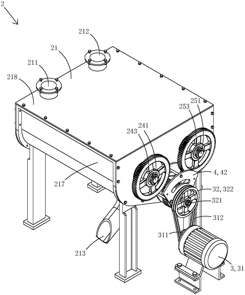
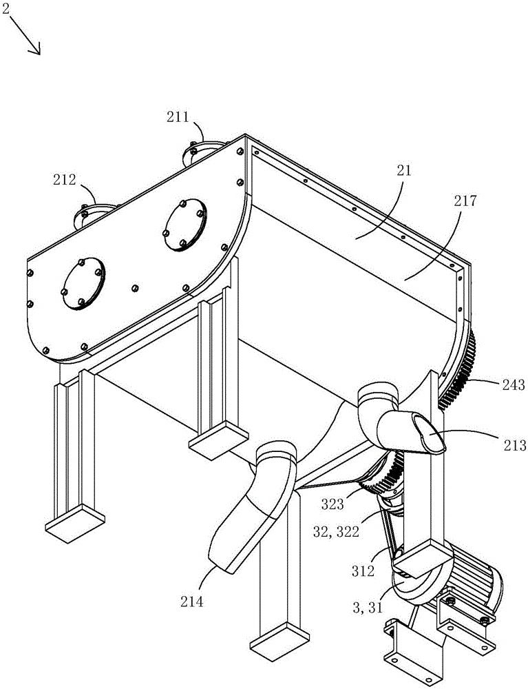
[0035] Figure 1 to Figure 19 A specific embodiment of the present invention is shown.

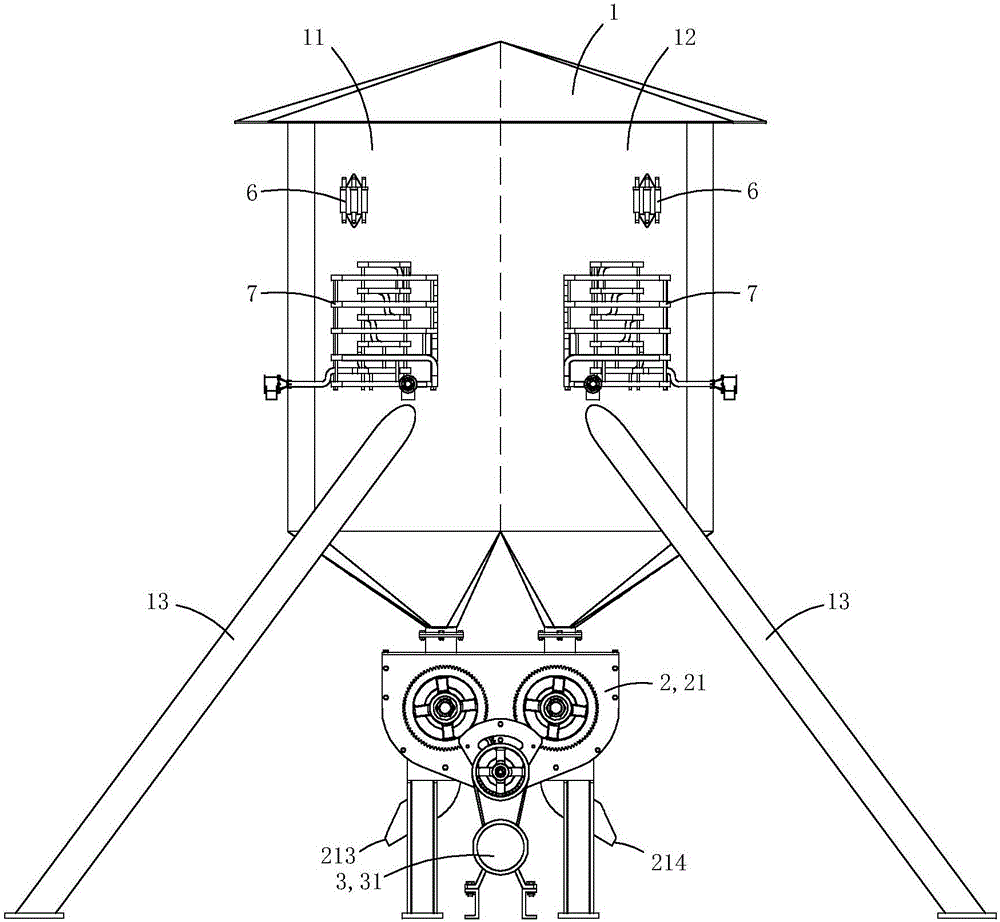
[0036] This embodiment is a two-body logistics warehouse, see figure 1 As shown, it includes a double-body warehouse 1 and a discharge device 2 arranged below the double-body warehouse.

[0037] The double-body warehouse 1 has a first warehouse 11 and a second warehouse 12 arranged side by side. The bottom of the first warehouse is cone-shaped, and the center of the bottom has a first discharge port; the bottom of the second warehouse is also cone-shaped, and its bottom There is a second outlet at the center. In this embodiment, the lower part of the double-body warehouse is provided with four support pillars 13 through which the double-body warehouse stands on the ground. In specific practice, it is also not necessary to support pillars, but to directly fix the double-body warehouse on the wall or the carrier, for example, the embodiment is used on a combine harvester.

[0038] see figure 1 , ...


PUM


Abstract

The invention discloses a logistics warehouse. The logistics warehouse comprises a double-body warehouse and a discharge device arranged below the double-body warehouse. The double-body warehouse is provided with a first warehouse and a second warehouse which are arranged side by side. A ventilation heat exchange system is arranged in each of the first warehouse and the second warehouse. Each ventilation heat exchange system comprises an exhaust fan, a suction fan and a ventilation pipeline. Each ventilation pipeline comprises an outer pipe air pipe, an inner ring air pipe and supporting rods for connecting and supporting pipe bodies. The inner ring air pipes are located in spaces defined by the outer ring air pipes. One end of each ventilation pipeline is connected with the corresponding exhaust fan, and the other end of each ventilation pipeline is connected with the corresponding suction fan. The discharge device comprises a first auger for discharging materials stored in the first warehouse, a second auger for unloading materials stored in the second warehouse, and a driving device for driving the first auger and the second auger to rotate. The structure is compact and reasonable.

Description

Technical field [0001] The invention belongs to the technical field of logistics storage structure design, and specifically relates to a logistics warehouse. Background technique [0002] At present, traditional logistics warehouses or large industrial warehouses used to store granular materials, such as warehouses used to store granular materials such as plastic particles, feed pellets, rice, rice, soybeans, corn, etc., are mostly designed as a single unit, which can only be used at the same time. Store one kind of material with single function. There are also some logistics warehouses using a double-body design, but two separate unloading devices are used for unloading, which leads to the disadvantages of larger area and higher cost. In addition, the current level of informatization of traditional warehouses is relatively low, and it is impossible to conduct effective and timely exploration and monitoring of the storage materials in the warehouse, especially the deep-seated st...

Claims


Application Information

Patent Timeline
IPC IPC(8): B65D88/28B65D90/00F24F7/06
CPCB65D88/28B65D90/00F24F7/06
Inventor 申俊
Owner SUZHOU JUNFENGCHEN ELECTRONICS TECH
Learn More