
Thermal protection structure for leading edge of hypersonic vehicle

A technology of thermal protection structure and aircraft, applied in aircraft parts, fuselage, transportation and packaging, etc., can solve the problem of difficult cooling of leading edge parts, and achieve the effect of saving coolant, making up for weakening, and strengthening the overall structural strength

Active Publication Date: 2017-03-22
TSINGHUA UNIV
View PDF7 Cites 32 Cited by
  • Summary
  • Abstract
  • Description
  • Claims
  • Application Information

AI Technical Summary

Problems solved by technology

These cooling methods can better realize the thermal protection of the super-combustion engine and even the fuselage of the super aircraft, but it is difficult to effectively cool the leading edge components

Method used


Image

  • Thermal protection structure for leading edge of hypersonic vehicle
  • Thermal protection structure for leading edge of hypersonic vehicle
  • Thermal protection structure for leading edge of hypersonic vehicle

Examples


Embodiment Construction

[0017] The present invention will be described in detail below in conjunction with the accompanying drawings and embodiments.

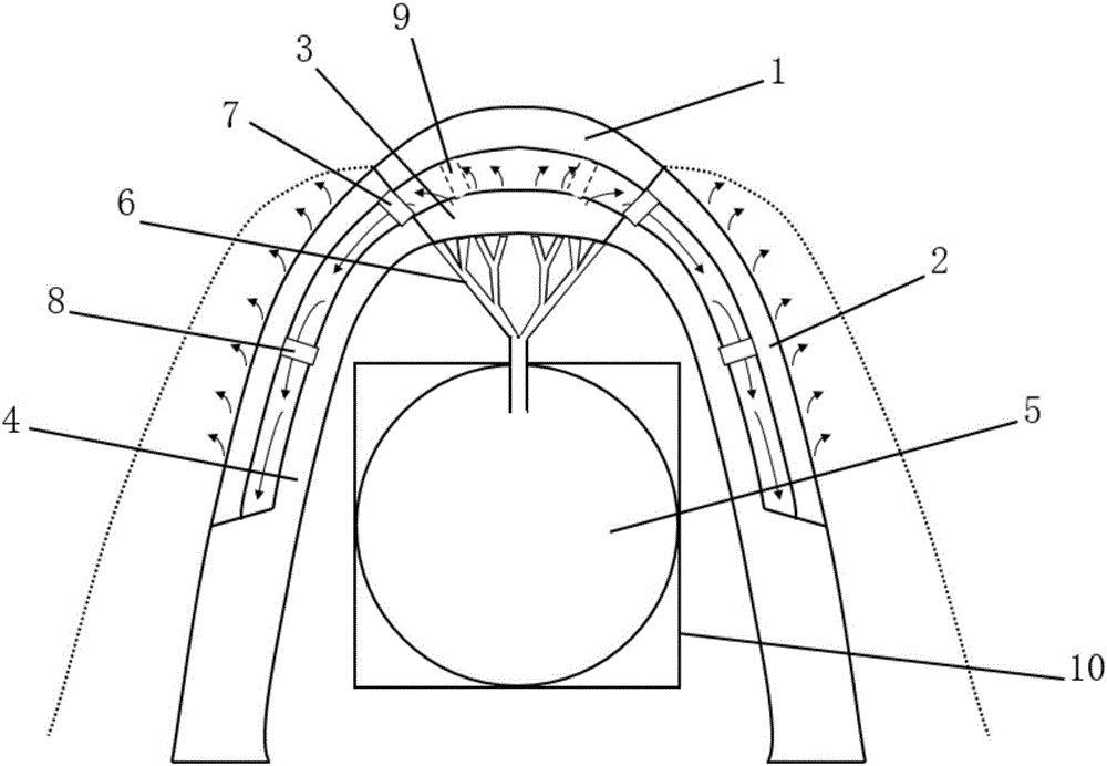
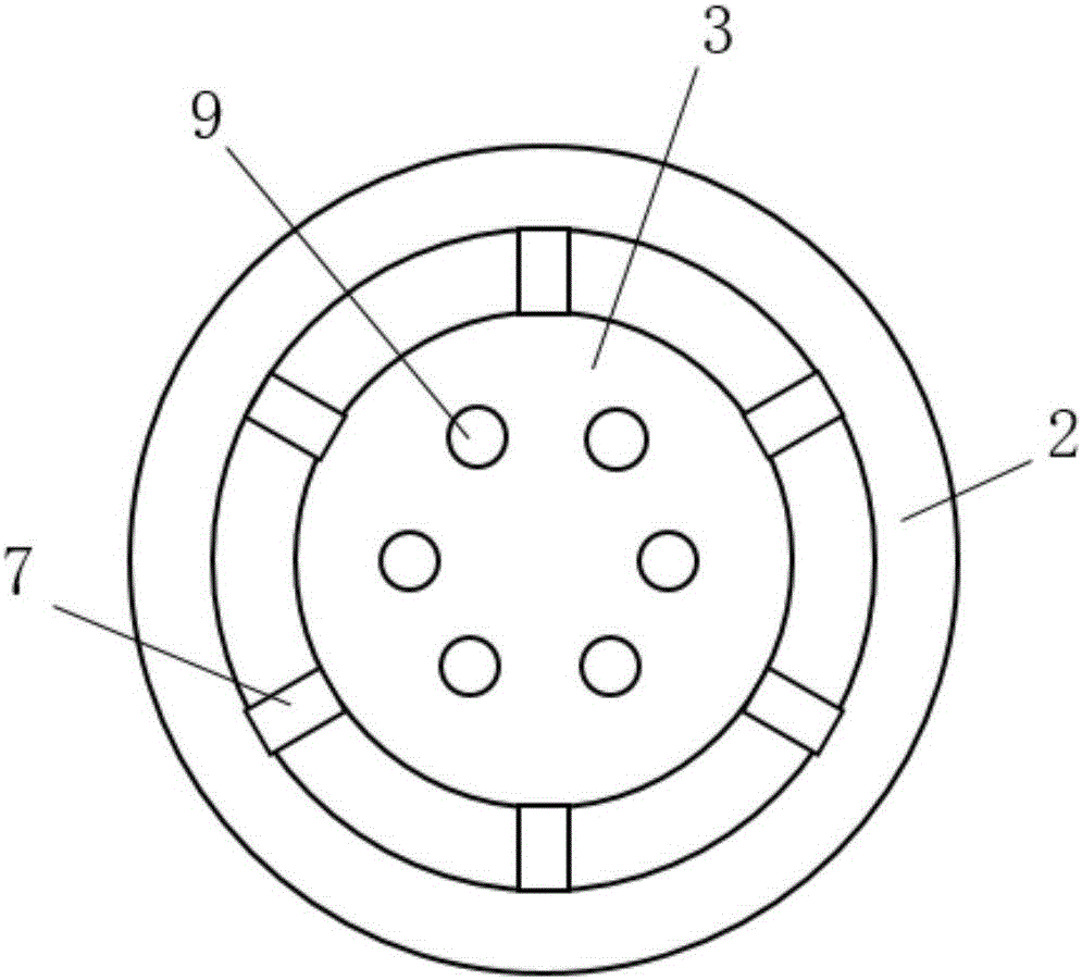
[0018] Such as figure 2 As shown, the present invention proposes a thermal protection structure at the leading edge of a hypervehicle, the thermal protection structure consists of an outer shell layer and an inner wall layer from outside to inside. The shell layer includes a head cover 1 at the top of the front edge and a front edge side wall shell 2 fixedly connected to the head cover 1, wherein the head cover 1 is made of a high temperature resistant material (such as carbon / carbon composite material), and the front edge side The wall shell 2 is made of a steel based porous material. The inner wall layer includes a head cover 3 arranged corresponding to the head cover 1 and a metal shell 4 fixedly connected with the head cover 3 and arranged corresponding to the front edge side wall shell 2, wherein the head cover 3 is made of a steel-based porous...


PUM


Abstract

The invention relates to a thermal protection structure for the leading edge of a hypersonic vehicle. The thermal protection structure is sequentially composed of a shell layer and an inner wall layer from outside to inside. The shell layer comprises a first head cap located at the top end of the leading edge and a leading edge side wall shell fixedly connected with the first head cap. The first head cap is made from high temperature resistant materials, and the leading edge side wall shell is made from steel-based porous materials. The inner wall layer comprises a second head cap arranged corresponding to the first head cap, and a metal shell fixedly connected with the second head cap and arranged corresponding to the leading edge side wall shell. The second head cap is made from steel-based porous materials. A cooling channel is formed between the inner wall layer and the shell layer which are connected through a plurality of supporting ribs. A water storage capsule used for storing coolants is arranged inside the inner wall layer and connected with the second head cap through a tree-shaped capillary fractal structure and provides the coolants needed for transpiration cooling for the second head cap.

Description

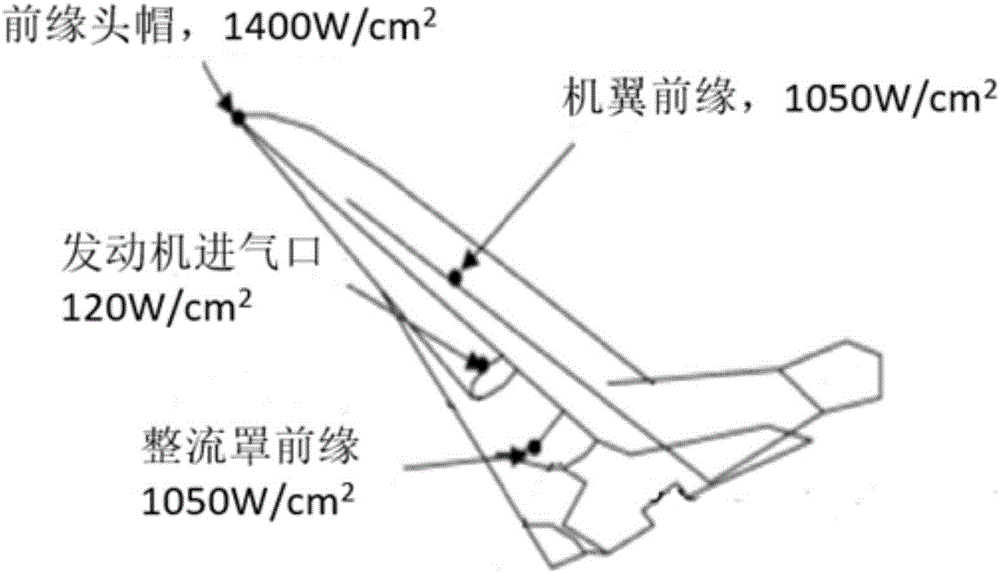
technical field [0001] The invention relates to a heat protection structure for the leading edge of a hyper-vehicle, belonging to the technical field of aircraft heat protection. Background technique [0002] Aerospace technology, as an important symbol of a country's economy, military, and international status, has been heavily invested in many countries in the world, and has driven the prosperity and development of industries in related fields. In order to meet higher and faster flight requirements, the parameters of aerospace vehicles have been continuously improved, and the representative one is the development of hypersonic (Ma>5, Ma is the Mach number) aircraft. Such as figure 1 As shown, under the flight conditions of a typical hypersonic vehicle (Mach number Ma=6.5, the total temperature of the airflow is 1800K), some key leading edge parts of the hypersonic vehicle, such as the leading edge cap, the leading edge of the wing, and the engine intake The mouth, the...

Claims


Application Information

Patent Timeline
Patent Type & Authority Applications(China)
IPC IPC(8): B64C1/00B64C1/38
CPCB64C1/00B64C1/38
Inventor 姜培学胥蕊娜祝银海黄干廖致远陆韬杰
Owner TSINGHUA UNIV
Learn More