Coal char and urea or ammonium bicarbonate mixed pyrolysis cycle reduction system for nitrogen oxides

A technology of ammonium bicarbonate and mixed pyrolysis, applied in the field of nitrogen oxide removal system, can solve problems such as boiler efficiency decline, poor contact between reducing agent and flue gas, water wall tube burst, etc.

Active Publication Date: 2018-12-14
HARBIN INST OF TECH
View PDF3 Cites 0 Cited by
  • Summary
  • Abstract
  • Description
  • Claims
  • Application Information

AI Technical Summary

Problems solved by technology

[0004] The present invention aims to solve the problem that the reducing agent solution is sprayed into the boiler in the existing SNCR technology, which may cause the efficiency of the boiler to decrease due to water evaporation and heat absorption, unstable atomization or atomization deterioration leading to water wall tube bursting, and reducing agent and smoke To solve problems such as poor gas contact, thus providing a system for reducing nitrogen oxides in a mixed pyrolysis cycle of coal char and urea or ammonium bicarbonate

Method used


Image

  • Coal char and urea or ammonium bicarbonate mixed pyrolysis cycle reduction system for nitrogen oxides
  • Coal char and urea or ammonium bicarbonate mixed pyrolysis cycle reduction system for nitrogen oxides
  • Coal char and urea or ammonium bicarbonate mixed pyrolysis cycle reduction system for nitrogen oxides

Examples


specific Embodiment approach 1

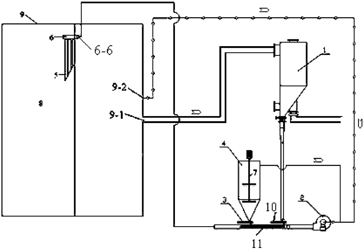
[0020] Specific implementation mode one: as Figure 1-8 , this embodiment is a system for reducing nitrogen oxides in a mixed pyrolysis cycle of coal char and urea or ammonium bicarbonate, specifically consisting of a boiler 9, a first-stage pre-dust collector 1, an induced draft fan 2, a first feeder 3, a second It consists of a feeder 10, a reducing agent storage tank 4, an agitator 7, a pipeline 11, a trough array mixer 5 and a distribution header 6;

[0021] The distribution header 6 is composed of the first straight pipe 6-4, the second straight pipe 6-1, the third straight pipe 6-2, the fourth straight pipe 6-7, the fifth straight pipe 6-5 and 16 Composed of three nozzles 6-3; the first straight pipe 6-4 and the second straight pipe 6-1 are arranged in parallel, the third straight pipe 6-2, the fourth straight pipe 6-7 and the fifth straight pipe 6-5 are arranged in parallel , the third straight pipe 6-2, the fourth straight pipe 6-7 and the fifth straight pipe 6-5 are ...

specific Embodiment approach 2

[0031] Embodiment 2: The difference between this embodiment and Embodiment 1 is that the boiler 9 is an industrial boiler. Others are the same as the first embodiment.

specific Embodiment approach 3

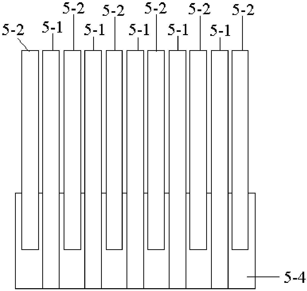
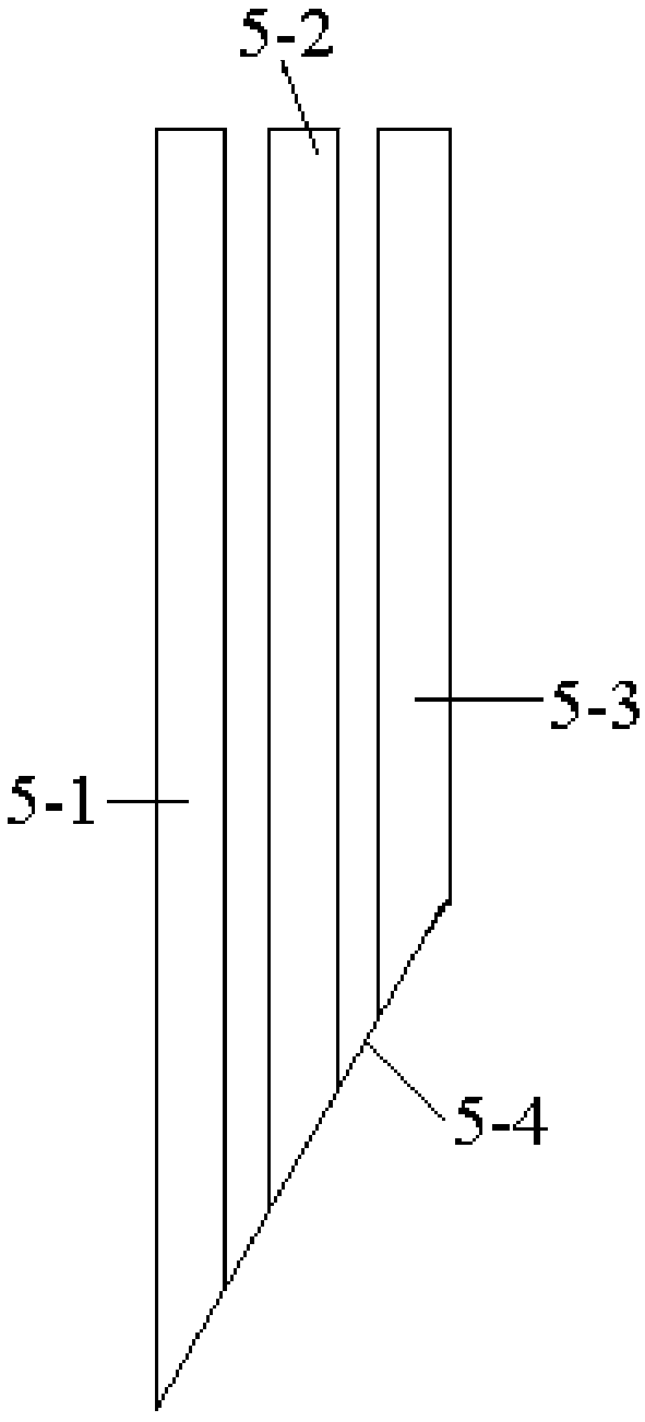
[0032] Embodiment 3: The difference between this embodiment and Embodiment 1 is that the material of the trough array mixer 5 is high temperature resistant metal. Others are the same as the first embodiment.


PUM


Abstract

The invention relates to a nitrogen oxide removal system, particularly relates to a system for cyclic reduction of nitrogen oxides by mixed pyrolysis of coke and urea or ammonium bicarbonate and aims to solve problems of boiler efficiency decline caused by evaporation related heat absorption of moisture in reducing agent solution, water wall tube cracking caused by instability or deterioration in atomization, poor contact between a reducing agent and smoke and the like of existing SNCR (selective non-catalytic reduction) techniques. The system comprises a boiler, a pre-dedusting device, a draught fan, a reducing agent storage tank, a trough type array mixer and a distributing header. The trough type array mixer is fixed at a combustion chamber outlet of the boiler, and the distributing header is suspended above the trough type array mixer. The pre-dedusting device is communicated with a flue outlet of the boiler, an air inlet of the draught fan is communicated with a tail flue hole of the boiler, an air outlet of the draught fan is communicated with one end of a pipeline, the other end of the pipeline is communicated with the distributing header, a coke separation outlet of the pre-dedusting device and a discharging port of the reducing agent storage tank are communicated to the pipeline, and an upper hole of the reducing agent storage tank is communicated with the air inlet of the draught fan.

Description

technical field [0001] The invention relates to a nitrogen oxide removal system. Background technique [0002] Selective non-catalytic reduction refers to the reduction of nitrogen oxides in the flue gas to harmless nitrogen and water by spraying a reducing agent in the "temperature window" suitable for denitrification reaction without the action of a catalyst. This technology generally uses ammonia, urea or hydrogen acid in the furnace as a reducing agent to reduce NOx. The reducing agent only reacts with NOx in the flue gas, and generally does not react with oxygen. This technology does not use a catalyst, so this method is called Selective Non-Catalytic Reduction (SNCR). Since the process does not use a catalyst, a reducing agent must be added in the high temperature zone. The reducing agent is sprayed into the area where the temperature of the furnace is 850-1100°C, and it is rapidly thermally decomposed into NH 3 , react with NOx in the flue gas to form N 2 and wate...

Claims


Application Information

Patent Timeline
Patent Type & Authority Patents(China)
IPC IPC(8): B01D53/56B01D53/76B01D53/83
CPCB01D53/56B01D53/565B01D53/76B01D2251/20B01D2251/2062
Inventor 高建民栾积毅杜谦赵义军徐力赵广播吴少华秦裕琨
Owner HARBIN INST OF TECH
Why Eureka
Try Eureka