


Quick Research
Generate reliable direction feasibility study reports for your R&D in just a few steps.

Technical Q&A
Discover and master advanced knowledge NOW. Basics, ideas, possibilities, all at once.

Find Solutions
As an expert in R&D theories, this can generate solutions to your technical problems instantly.

Evaluate Feasibility
Analyze your overall solution with one click, know your potential R&D risks in advance.

Monitor Landscape
Get weekly tech updates, stay abreast of the latest tech innovations and key insights.
Multistage bridge connection projection system and multistage bridge connection projection method based on screen projection
A projection system and projection technology, which are applied in the direction of using the image reproducer of the projection device, the parts and electrical components of the color TV, etc., can solve the problem that the distance between two mobile terminal equipment cannot be too far apart.
- Summary
- Abstract
- Description
- Claims
- Application Information
AI Technical Summary
Problems solved by technology
Method used
Image

Examples
no. 1 example
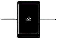
[0059] like image 3 As shown, the first embodiment of the present invention proposes a multi-stage bridge projection system based on screen projection, including: projection terminal A1, which sends out screen projection pictures; receiving terminal Ak (not shown), receives and displays screen projection pictures, At the same time, the screen projection picture is sent to the next receiving terminal Ak+1 (not shown). Where k is any number from 2 to n, and n is a positive integer greater than 2. The screen projection picture sent by the projection terminal A1 is the display content currently being played. After sending it to the receiving terminal Ak, the receiving terminal displays the screen projection picture and sends the screen projection picture to the next receiving terminal Ak+1. It can be seen that the multi-stage bridged projection system is constructed by the projection terminal and at least two receiving terminals Ak, so that long-distance transmission of screen p...
no. 2 example
[0062] like Figure 7 As shown, on the basis of the first embodiment, the receiving terminal Ak in the multi-stage bridge projection system based on screen projection provided by this embodiment is specifically used to: determine whether the receiving terminal is the last receiving terminal; if the receiving terminal If it is not the last receiving terminal, then receive and display the screen projection picture, and send the screen projection picture to the next receiving terminal at the same time. Therefore, when the receiving terminal Ak receives the link transmission request, it judges whether the receiving terminal itself is the last receiving terminal according to the user's input instruction. After receiving the user's response, it will make a corresponding judgment.
[0063] Further, such as Figure 7 As shown, the receiving terminal Ak is further configured to: when it is judged that the receiving terminal is the last receiving terminal, the operation to be performe...
no. 3 example
[0065] like Figure 4 As shown, on the basis of the first embodiment and the second embodiment, the receiving terminal in the multi-level bridge projection system based on screen projection in this embodiment is also used to: receive different screens sent by multiple projection terminals Projection screens, and display different screen projection screens in split screens. The split screen display area can be set by the user, as shown in the division of the split screen area in the figure. The upper screen and the lower screen can be used as relay terminals to maintain their own transmission link. In addition, the projecting terminal and the receiving terminal can each maintain multiple transmission links, that is, the projecting terminal can maintain multiple transmission links, so as to project the projection screen to multiple receiving terminals at the same time, and the receiving terminal can also receive and maintain multiple different transmission links. The transmissi...
PUM
 Abstract
Description
Claims
Application Information
 - R&D Engineer
- R&D Manager
- IP Professional
- Industry Leading Data Capabilities
- Powerful AI technology
- Patent DNA Extraction
Browse by: Latest US Patents, China's latest patents, Technical Efficacy Thesaurus, Application Domain, Technology Topic, Popular Technical Reports.
© 2024 PatSnap. All rights reserved.Legal|Privacy policy|Modern Slavery Act Transparency Statement|Sitemap|About US| Contact US: help@patsnap.com