
Patsnap Eureka
For R&D, Patsnap Eureka makes reading and utilizing patents & technical documents easy.
Patsnap Eureka AIR
Designed for self-driven R&D workflows. Generate viable solutions, solve complex R&D challenges, empower your innovation with AI.

Patsnap Eureka Materials
Designed for material experts only. Revolutionize your material R&D, from search, analyze, to developing new materials.

TechResearch
Generate reliable direction feasibility study reports for your R&D in just a few steps.

TechSeek
Discover and master advanced knowledge NOW. Basics, ideas, possibilities, all at once.

TechMind
As an expert in R&D Theories, TechMind can generates customized viable solutions instantly.

TechRisk
Analyze your overall solution with one click, know your potential R&D risks in advance.

TechMonitor
Get weekly tech updates, stay abreast of the latest tech innovations and key insights.
Underwater acoustic sensor network routing algorithm and system using harmonic field
An underwater acoustic sensing and routing technology, applied in transmission systems, digital transmission systems, network topology, etc., can solve problems such as failure to find routing
- Summary
- Abstract
- Description
- Claims
- Application Information
AI Technical Summary
Problems solved by technology
Method used
Image


Examples
Embodiment 1
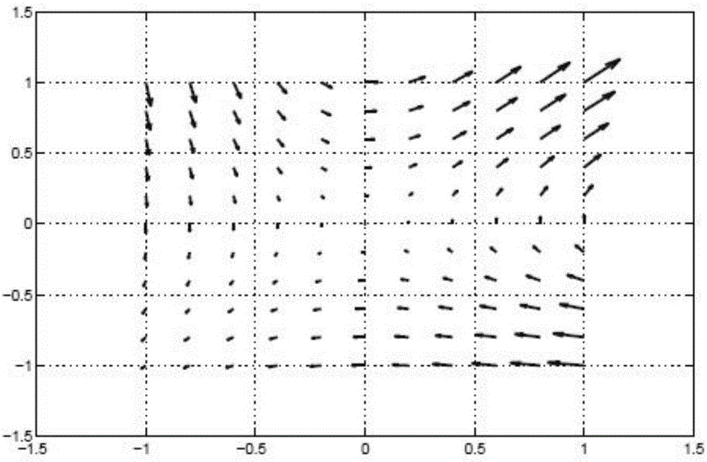
[0027] This implementation process uses the potential field theory, that is, the harmonic potential field method to obtain the routing of the underwater wireless sensor network; the harmonic potential field is a method based on the harmonic function, which overcomes the three-dimensional space path planning through the harmonic function and boundary conditions Minimal point problems in , without constant path maintenance.
[0028] According to potential field theory, the harmonic function is the solution to the following Laplace equation:
[0029]
[0030] where φ is a scalar representing the potential value, x i is the i-th dimension Cartesian coordinates, and n is the dimension of the space. By solving the above Laplace equation, what is obtained is a continuous potential function φ, which represents a path or route.
[0031] Such as figure 1 As shown, the specific implementation steps of the underwater acoustic sensor network routing algorithm provided in this embodim...
Embodiment approach
[0044] As a preferred embodiment of constructing a route from the sending node to the gateway node, that is, to define the route according to the underwater three-dimensional grid, the method includes:
[0045] If there is a sensor node in the underwater three-dimensional grid that the continuous curve of the route passes through, then the sensor node is selected as the relay node of the route;
[0046] If there are multiple sensor nodes in the underwater three-dimensional grid, the sensor node closest to the curve is selected as the relay node of the route;
[0047] If the sending node, relay node, and gateway node cannot form a complete route from the sending node to the gateway node, adjust the potential of the local minimum point, and then use the selected relay node until the sending node, relay node, gateway node The node can form a complete route from the sending node to the gateway node.
[0048] In practice, it is assumed that the topology of the network is known in ...
Embodiment 2
[0053] On the basis of Embodiment 1, this Embodiment 2 also provides an underwater acoustic sensor network routing system, including:
[0054] A sending node and a gateway node; where the sending node and the gateway node are suitable for establishing an underwater acoustic sensor network route.
[0055] The routing of the underwater acoustic sensor network constructed in the second embodiment is as described in the first embodiment.
PUM
 Abstract
Description
Claims
Application Information
 - R&D Engineer
- R&D Manager
- IP Professional
- Industry Leading Data Capabilities
- Powerful AI technology
- Patent DNA Extraction
Browse by: Latest US Patents, China's latest patents, Technical Efficacy Thesaurus, Application Domain, Technology Topic, Popular Technical Reports.
© 2024 PatSnap. All rights reserved.Legal|Privacy policy|Modern Slavery Act Transparency Statement|Sitemap|About US| Contact US: help@patsnap.com