
Digital array radar optical fiber transmission network

A digital array radar and optical fiber transmission technology, which is applied in the direction of optical fiber transmission, transmission system, electromagnetic network arrangement, etc., can solve the problems of unstable communication, high design cost and maintenance cost, and inability to realize multi-point links, so as to avoid signal phase Effects of jitter problems, improvement of communication stability, reduction of design cost and maintenance cost

Inactive Publication Date: 2017-03-15
SHANGHAI SPACEFLIGHT INST OF TT&C & TELECOMM
View PDF4 Cites 1 Cited by
  • Summary
  • Abstract
  • Description
  • Claims
  • Application Information

AI Technical Summary

Problems solved by technology

[0004] The purpose of the present invention is to provide a digital array radar optical fiber transmission network to solve the problem that the existing digital array radar optical fiber transmission network cannot realize multi-point links and cause communication instability when multiple optical fibers transmit signals at the same time
[0005] The second purpose of the present invention is to provide a digital array radar optical fiber transmission network to solve the problem that the existing digital array radar optical fiber transmission network uses multiple multi-mode optical fibers to cause high design and maintenance costs

Method used


Image

  • Digital array radar optical fiber transmission network
  • Digital array radar optical fiber transmission network
  • Digital array radar optical fiber transmission network

Examples


Embodiment Construction

[0021] Referring to the drawings showing the present embodiment, the present invention will be described in more detail below. However, this invention may be embodied in many different forms and should not be construed as limited to the embodiments set forth herein. Rather, these embodiments are provided so that this disclosure will be thorough and complete, and will fully convey the scope of the invention to those skilled in the art.

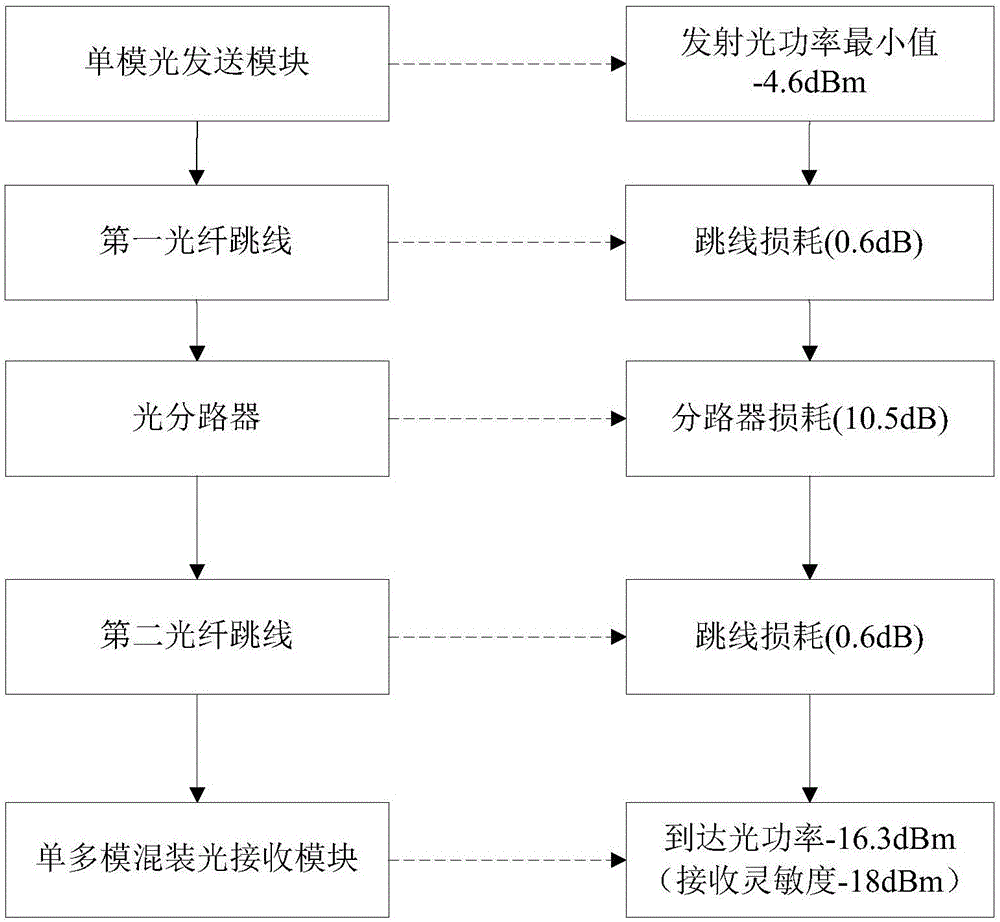
[0022] Such as figure 1 As shown, the digital array radar optical fiber transmission network provided by the present invention is used to establish data communication between digital T / R components and signal processing components. It only includes a single-mode optical fiber 11 at the sending end 10, and the transmission network 20 includes An optical splitter 21. Wherein, the single-mode optical fiber 11 is connected to the signal processing component of the transmitting end 10 , and the optical splitter 21 is connected to the digital T / R c...


PUM


Abstract

The invention provides a digital array radar optical fiber transmission network which is used to establish data communication between a digital T / R assembly and a signal processing assembly. The network comprises a single mode fiber connected to the signal processing assembly and an optical branching device connected to the established digital T / R assembly. The single mode fiber is used for sending a signal from the signal processing assembly to the branching device. The optical branching device divides the signal into several paths and then transmits to the digital T / R assembly. The single mode fiber and the optical branching device are connected in a jumper wire mode through one first optical fiber. The optical branching device and the digital T / R assembly are connected in the jumper wire mode through several second optical fibers. The transmission network adopts the single mode fiber and the optical branching device. Through an system improvement, ''one-to-many'' network interconnection is realized so that design cost and maintenance cost are greatly reduced, a signal phase jitter problem brought by multi-optical-fiber transmission is avoided and communication stability is increased.

Description

technical field [0001] The invention relates to the technical field of optical fiber transmission network design of digital array radar, in particular to a digital array radar optical fiber transmission network for establishing data communication between digital T / R components and signal processing combinations. Background technique [0002] In the digital array radar, the data communication rate between the digital T / R component and the signal processing combination is higher than 1.25Gbps / channel, and the traditional copper medium communication cannot meet the design requirements. Based on the special requirements of the application environment of digital array radar, such as the high-speed transmission of radar signals in the environment of military temperature, salt spray, mold, and sand dust, at present, multimode optical fibers are commonly used in engineering to realize data communication. At the beginning of the development of this technology, the transmission speed ...

Claims


Application Information

Patent Timeline
Patent Type & Authority Applications(China)
IPC IPC(8): H04B10/25H04B10/27G01S7/02
CPCG01S7/02H04B10/27H04B10/25891
Inventor 岳伟赵婵娟
Owner SHANGHAI SPACEFLIGHT INST OF TT&C & TELECOMM
Learn More