
Efficient cable laying device

A laying device and cable technology, applied in the direction of cable installation, cable installation, cable laying equipment, etc., can solve the problems of increasing construction difficulty, inability to calculate laying length, time-consuming and labor-intensive, etc., to reduce laying difficulty and facilitate recording usage Effect

Inactive Publication Date: 2017-03-15
KUNMING KUNBAO WIRE & CABLE MFG
View PDF5 Cites 8 Cited by
  • Summary
  • Abstract
  • Description
  • Claims
  • Application Information

AI Technical Summary

Problems solved by technology

[0004] The purpose of the present invention is to provide a high-efficiency cable laying device to solve the problems that the laying length cannot be calculated, time-consuming and labor-intensive, and construction difficulty is increased in the existing manual cable laying process

Method used


Image

  • Efficient cable laying device
  • Efficient cable laying device
  • Efficient cable laying device

Examples


Embodiment 1

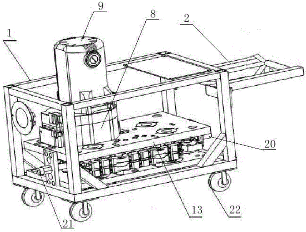
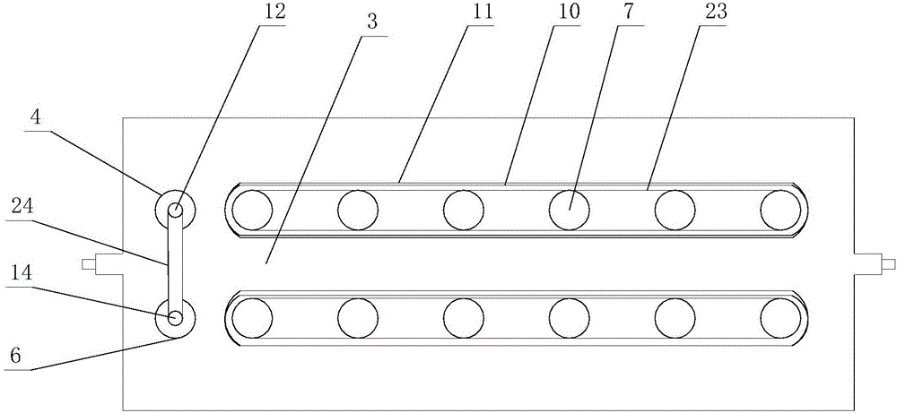
[0024] Such as Figure 1 to Figure 4 As shown, the high-efficiency cable laying device includes a support 1 that is detachably connected to each other and a cable rack 2 for preventing cables; two transmission groups parallel to each other are provided along the length direction of the support 1; a cable channel is formed between the two transmission groups 3. A counting mechanism is provided at the outlet end of the cable channel 3 on the bracket 1; the counting mechanism includes a driven wheel 4, a counter 5 and a counting wheel 6 connected to the counter 5; the channel formed between the driven wheel 4 and the counting wheel 6 and the cable The center line of channel 3 coincides; the output terminal of counter 5 is connected with the signal input terminal of controller 18 .

[0025] Wherein, the transmission group includes a plurality of transmission wheels 7 arranged in sequence, and all transmission wheels 7 are connected to each other by chains; any transmission wheel 7...

Embodiment 2

[0030] Such as Figure 1 to Figure 4 As shown, the difference between this embodiment and Embodiment 1 is that the top of the lower space 16 is provided with a camera 17; the output end of the camera 17 is connected with a controller 18 and a display 19 in turn; If there is any problem during use, you can first check the surveillance camera to check the problem, making maintenance more convenient.

[0031] Such as Figure 1 to Figure 4 As shown, when the present invention is in use, the cable enters the cable passage 3 from the wire entry hole 20, and the motor 9 drives the transmission wheel 7 to rotate so that the cable advances in the cable passage 3, enters between the counting wheel 6 and the driven wheel 4, and passes through the counting wheel 6 start counting, and the counting enters the display 19 display, which is convenient for people to check, and then the cable passes through the outlet hole 21; among the present invention, the cable passage 3 made up of the moto...


PUM


Abstract

The invention discloses an efficient cable laying device, and mainly solves the problems that laying length cannot be calculated in the existing manual cable laying process and time and labor are consumed and the construction difficulty is increased. The efficient cable laying device comprises a support and a cable rack used for preventing a cable, wherein the support and the cable rack are detachably interconnected. Two mutually parallel transmission groups are arranged along the length direction of the support. A cable channel is formed between the two transmission groups. The wire outlet end of the cable channel on the support is provided with a counting mechanism. The counting mechanism comprises a driven wheel, a counter and a counting wheel which is connected with the counter. A channel formed between the driven wheel and the counting wheel is overlapped with the center line of the cable channel. With application of the scheme, the objectives that cable laying is time-saving and labor-saving and reduces the construction difficulty can be achieved so that the efficient cable laying device has high practical value and popularization value.

Description

technical field [0001] The invention relates to the field of cable laying, in particular to a high-efficiency cable laying device. Background technique [0002] The cable is usually a similar rope twisted by several or groups of wires (at least two in each group). Each group of wires is insulated from each other and is often twisted around a center. Covering cables have the characteristics of internal energization and external insulation. Cables are widely used in many industries such as oil fields, mines, building construction, machinery manufacturing units, scientific research units, ports, shopping malls, hotels, road and bridge construction, etc. With the increasing industrial demand The more diversified, the proportion will increase. [0003] Cables are usually laid by manually pulling out the cables. During the laying process, the laid cables cannot be counted. The cables are placed on the shelf in circles. It requires a lot of manpower to pull the cables, so it is no...

Claims


Application Information

Patent Timeline
IPC IPC(8): H02G1/08
CPCH02G1/085
Inventor 杨春贵刘凤梅赵影赵明祥袁亮
Owner KUNMING KUNBAO WIRE & CABLE MFG
Learn More