
A Transient Electromagnetic Inversion Method Based on Transverse Smoothness Constraint

A transient electromagnetic and lateral smoothing technology, applied in the field of geophysical exploration, can solve problems such as the inability to impose constraints on adjacent measuring points, and achieve the effects of real and reliable inversion imaging results, suppression of jumps, and regularization and iteration stability.

Active Publication Date: 2019-03-15
INST OF ELECTRONICS CHINESE ACAD OF SCI
View PDF6 Cites 0 Cited by
  • Summary
  • Abstract
  • Description
  • Claims
  • Application Information

AI Technical Summary

Problems solved by technology

Current regularized inversion methods are limited to single-point inversion and cannot impose constraints between adjacent measurement points

Method used


Image

  • A Transient Electromagnetic Inversion Method Based on Transverse Smoothness Constraint
  • A Transient Electromagnetic Inversion Method Based on Transverse Smoothness Constraint
  • A Transient Electromagnetic Inversion Method Based on Transverse Smoothness Constraint

Examples


example

[0073] In this embodiment, the transient electromagnetic secondary field data is inverted through the described transverse smoothness constraint algorithm.

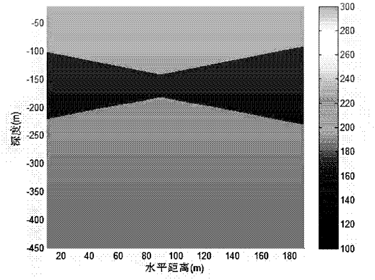
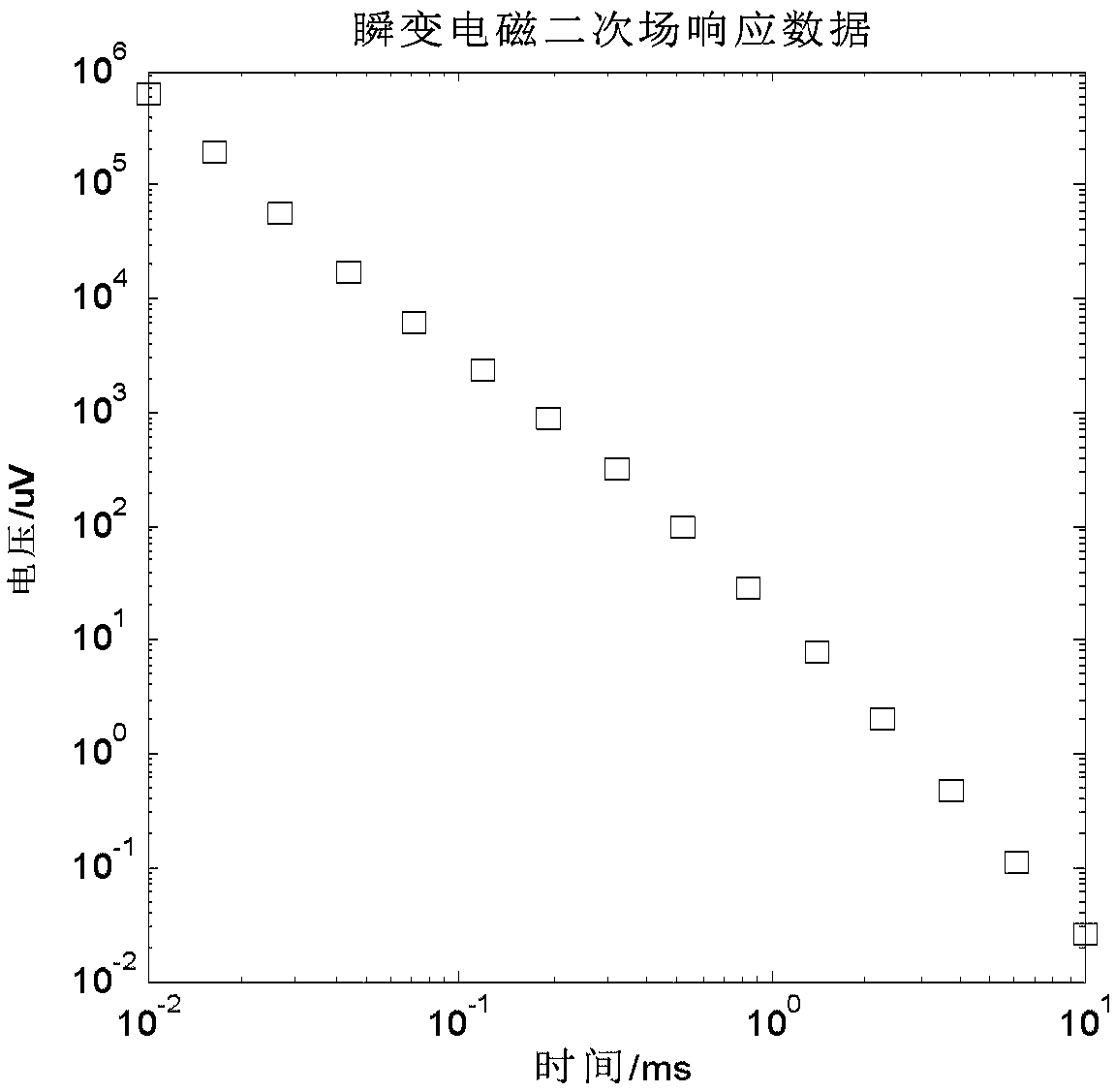
[0074] (1) Input the secondary field data measured by the transient electromagnetic method. Set up the terrain model as figure 1 As shown, the electrical parameters use the resistivity of conductive geological bodies, which are 300Ωm, 100Ωm, and 300Ωm respectively. The observation data at each measuring point should have attenuation characteristics, such as figure 2 shown.

[0075] (2) Input the inversion parameters and build the initial model. The number of turns of the transmitting coil is 1, the transmitting current is 5A, the transmitting radius R=50m, the offset distance of the observation point is r=0m, and the effective area of ​​the receiving coil is 2000m 2 . Assume that the number of measurement points is M=19, the inversion model is 30 layers, and the thickness growth ratio is h i+1 / h i =1.04, the thic...


PUM


Abstract

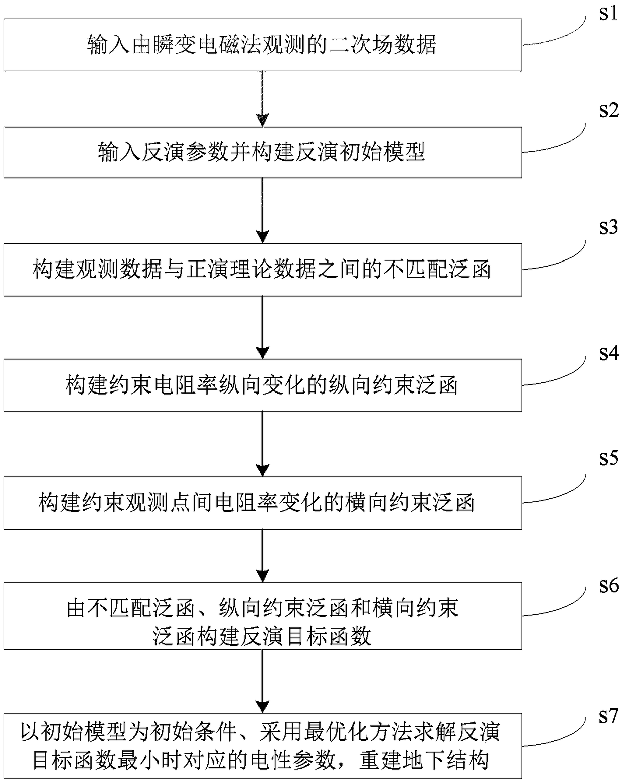
The invention discloses a transient electromagnetic inversion method based on transverse smooth constraint and is applied to the earth exploration field. The method comprises steps that S1, a primary pulse magnetic field is emitted to the underground, a secondary magnetic field excited by induction eddy current generated by an underground conductive geologic body under the excitation action of the primary pulse magnetic field is measured, secondary magnetic field data acquired through measurement is taken as observation data; S2, an initial inversion model is constructed; S3, a mismatching functional between the observation data and forward theory data is constructed; S4, a vertical constraint functional for constraining electric parameter change of the conductive geologic body is constructed; S5, a transverse constraint functional for constraining electric parameter change of the conductive geologic body among measurement points is constructed; S6, an inversion target function is constructed on the basis of the mismatching functional, the vertical constraint functional and the transverse constraint functional; and S7, the initial inversion model is taken as initial conditions, an electric parameter corresponding to a smallest inversion target function value is solved, and the underground structure is reconstructed according to the electric parameter. The method is advantaged in that the underground structure acquired on the basis of inversion imaging results is more accurate and reliable.

Description

technical field [0001] The invention relates to the field of geophysical exploration, and more specifically, to a transient electromagnetic inversion method. Background technique [0002] As a powerful means of geophysical exploration, transient electromagnetic method can solve various geophysical problems such as mineral exploration, energy, engineering, hydrology, environmental geological survey, and archaeological exploration. It uses step waves or other pulse currents to emit a pulsed magnetic field underground, and the underground conductive geological body generates an induced eddy current under the excitation of the primary field, and then stimulates a secondary magnetic field. When the emission current is turned off, the primary field disappears, and the subsurface eddy current decays with time, and its decay time is related to the electrical parameters (volume, structure, buried depth, resistivity, conductivity, dielectric constant) of the conductive geological body...

Claims


Application Information

Patent Timeline
Patent Type & Authority Patents(China)
IPC IPC(8): G01V3/38G01V3/10
CPCG01V3/10G01V3/38
Inventor 武欣郭睿方广有
Owner INST OF ELECTRONICS CHINESE ACAD OF SCI
Learn More