Mineral particle swirling flow pneumatic conveying system

A pneumatic conveying system and mineral particle technology, applied in conveyors, conveying bulk materials, transportation and packaging, etc., can solve problems such as difficulty in adapting to the diversity of mineral particles, inability to realize swirl replenishment, and difficult adjustment of swirl intensity, etc. Achieve the effect of reducing the critical conveying speed, changing the speed, and reducing particle breakage

Inactive Publication Date: 2017-03-15
HENAN POLYTECHNIC UNIV
View PDF10 Cites 7 Cited by
  • Summary
  • Abstract
  • Description
  • Claims
  • Application Information

AI Technical Summary

Problems solved by technology

However, the existing swirl conveying technology generally can only generate swirl at the air inlet position, and cannot realize swirl replenishment during the conveying process, and the generated swirl intensity is not easy to adjust, and it is difficult to adapt to the diverse needs of the mineral particle conveying process. It still cannot effectively solve the problems of particle deposition, pipeline blockage, pipeline wear and material crushing

Method used


Image

  • Mineral particle swirling flow pneumatic conveying system
  • Mineral particle swirling flow pneumatic conveying system
  • Mineral particle swirling flow pneumatic conveying system

Examples


Embodiment Construction

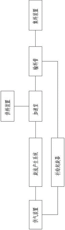
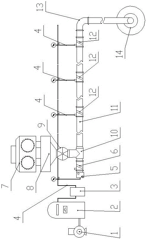
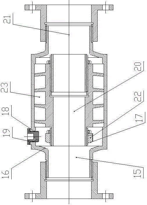
[0022] Such as Figure 1-4 As shown, a mineral particle cyclone pneumatic conveying system of the present invention includes an air supply device, a feed device, a gas delivery pipe 4, a supply spinner 12, an acceleration chamber 10, a material delivery pipe 11 and a material collection device 14, for supplying A swirl flow generation system is provided between the gas device and the acceleration chamber 10;

[0023] The air supply device includes a fan 1, an air storage tank 2 and a dryer 3, the feed device includes a crusher 7, a buffer silo 8 and a rotary feeder 9, and the swirl generation system includes a gas rectifier 5 and an initial starting Spinner 6;

[0024] The air outlet of the fan 1 is connected to the air inlet of the gas storage tank 2, the air outlet of the air storage tank 2 is connected to the air inlet of the dryer 3, and the air outlet of the dryer 3 is respectively rectified with the gas rectifier 5 through the air pipe 4. The air inlet is connected wit...


PUM


Abstract

A mineral particle swirling flow pneumatic conveying system comprises an air supply device, a feeding device, air conveying pipes, a swirling flow generating system, replenishment swirlers, an accelerating chamber, a conveying pipe and a collecting device. An air outlet of the air supply device is connected with an air inlet of the swirling flow generating system and replenishment air inlets of the replenishment swirlers separately. An air outlet of the swirling flow generating system is connected with an air inlet of the accelerating chamber. A discharging outlet of the feeding device is connected with a feeding inlet of the accelerating chamber. An air and material outlet of the accelerating chamber is connected with an air and material inlet of the conveying pipe. A plurality of replenishment swirlers are evenly arranged at intervals on the conveying pipe in the direction of conveying. Each replenishment swirler is arranged in front of a corresponding section of bent pipe of the conveying pipe. An air and material outlet of the conveying pipe is connected with a feeding inlet of the collecting device. According to the mineral particle swirling flow pneumatic conveying system, the critical conveying speed of mineral particles is reduced, particle deposition and pipeline clogging are relieved, bent pipe abrasion and particle damaging are mitigated, the service life of conveying pipelines is prolonged, and the safe and efficient long-distance delivery of the mineral particles in the pipelines is achieved.

Description

technical field [0001] The invention relates to the technical field of pneumatic conveying, in particular to a mineral particle pneumatic conveying system capable of generating swirling flow and replenishing the swirling flow. Background technique [0002] Pneumatic conveying is a transportation method that uses the kinetic energy or pressure energy of the gas in the pipeline to transport the solid granular material according to the predetermined pipeline. According to the pressure state of the gas, it can be divided into positive pressure conveying and negative pressure conveying. According to the mass ratio of material and gas, it can be Divided into dilute phase transport and dense phase transport. Mineral particle pneumatic conveying technology requires safe, efficient and long-distance transportation of materials in the pipeline, and ensures that the materials will not be significantly broken and the pipeline will not be blocked. Usually, the positive pressure conveying...

Claims


Application Information

Patent Timeline
Patent Type & Authority Applications(China)
IPC IPC(8): B65G53/16B65G53/58
CPCB65G53/16B65G53/58
Inventor 刘瑜周甲伟韩晓明罗晨旭徐永亮
Owner HENAN POLYTECHNIC UNIV
Why Eureka
Try Eureka