


Quick Research
Generate reliable direction feasibility study reports for your R&D in just a few steps.

Technical Q&A
Discover and master advanced knowledge NOW. Basics, ideas, possibilities, all at once.

Find Solutions
As an expert in R&D theories, this can generate solutions to your technical problems instantly.

Evaluate Feasibility
Analyze your overall solution with one click, know your potential R&D risks in advance.

Monitor Landscape
Get weekly tech updates, stay abreast of the latest tech innovations and key insights.
Arc welding control method
一种控制方法、电弧焊接的技术,应用在电弧焊设备、焊接设备、制造工具等方向,能够解决焊接状态不稳定等问题,达到焊接状态稳定化的效果
- Summary
- Abstract
- Description
- Claims
- Application Information
AI Technical Summary
Problems solved by technology
Method used
Image

Examples
Embodiment approach 1
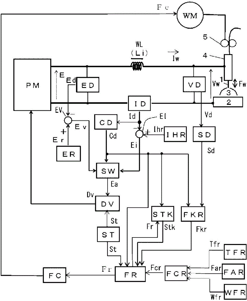
[0032] figure 1 It is a block diagram of a welding power source for implementing the arc welding control method according to Embodiment 1 of the present invention. The following reference figure 1 to illustrate the blocks.
[0033] The power supply main circuit PM receives a commercial power supply (not shown) such as 3-phase 200V as input, performs output control by inverter control or the like in accordance with a drive signal Dv described later, and outputs an output voltage E. Although not shown in the figure, this power supply main circuit PM includes a primary rectifier for rectifying a commercial power supply, a smoothing capacitor for smoothing the rectified direct current, and the aforementioned drive signal Dv for converting the smoothed direct current into a high-frequency alternating current. An inverter circuit for driving, a high-frequency transformer that steps down high-frequency AC to a voltage suitable for welding, and a secondary rectifier that rectifies t...
Embodiment approach 2
[0103] The invention of Embodiment 2 includes a push side feed motor for performing forward feed feed control in addition to the pull side feed motor for performing forward and reverse feed control of Embodiment 1, and the push side feed motor is controlled from the welding current. Accelerates with a slope during a predetermined acceleration period from the time when energization is started.
[0104] Figure 4 It is a block diagram of a welding power source for implementing the arc welding control method according to Embodiment 2 of the present invention. Figure 4 with the above figure 1 Correspondingly, mark the same blocks with the same symbols and their descriptions will not be repeated. Figure 4 exist figure 1 On the basis of the push side feed motor WM2, the acceleration period setting circuit TUR, the second feed speed setting circuit FR2 and the second feed control circuit FC2 are added. The following reference Figure 4 to illustrate these blocks.
[0105] The...
Embodiment approach 3
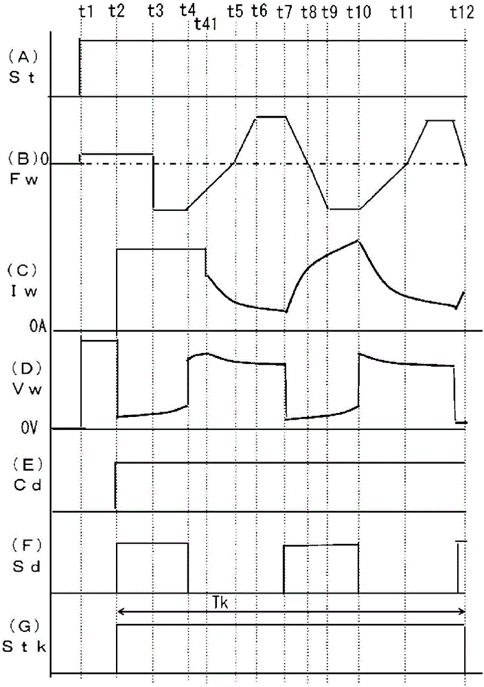
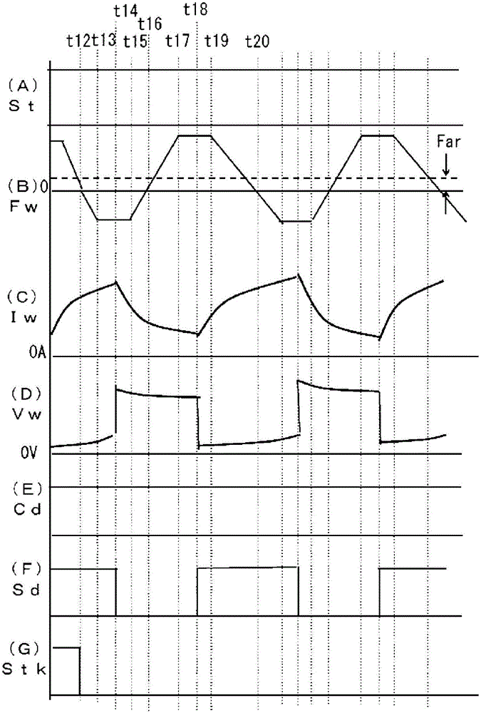
[0117] The invention of Embodiment 3 is in Embodiment 1 figure 2 The same operation during the transition welding period, image 3 Actions during steady-state welding in different scenarios. That is, in the invention of Embodiment 1, the waveform of the feed speed becomes a given type during the steady-state welding period, and the absence of an arc and the occurrence of a short circuit are triggered to switch between the forward feed period and the reverse feed of the feed speed. situation during the period. On the other hand, in the invention of Embodiment 3, the forward feed period and the reverse feed period of the feed speed are switched between the steady state welding period and the arc generation and the occurrence of a short circuit as triggers as in the transition welding period. .
[0118] Figure 6 It is a block diagram of a welding power source for implementing the arc welding control method according to Embodiment 3 of the present invention. Figure 6 with ...
PUM
 Abstract
Description
Claims
Application Information
 - R&D Engineer
- R&D Manager
- IP Professional
- Industry Leading Data Capabilities
- Powerful AI technology
- Patent DNA Extraction
Browse by: Latest US Patents, China's latest patents, Technical Efficacy Thesaurus, Application Domain, Technology Topic, Popular Technical Reports.
© 2024 PatSnap. All rights reserved.Legal|Privacy policy|Modern Slavery Act Transparency Statement|Sitemap|About US| Contact US: help@patsnap.com