
Mechanical-hydraulic double security locking hydraulic cylinder

A locking hydraulic cylinder and double insurance technology, applied in the direction of fluid pressure actuating device, etc., can solve the problems of insufficient hydraulic locking stability, limited operating position of piston rod, easy slippage of piston, etc., and achieve reliable dynamic balance function And safety locking function, to avoid pressure shock, to ensure the effect of service life

Active Publication Date: 2017-03-08
北京冶自欧博科技发展有限公司
View PDF6 Cites 4 Cited by
  • Summary
  • Abstract
  • Description
  • Claims
  • Application Information

AI Technical Summary

Problems solved by technology

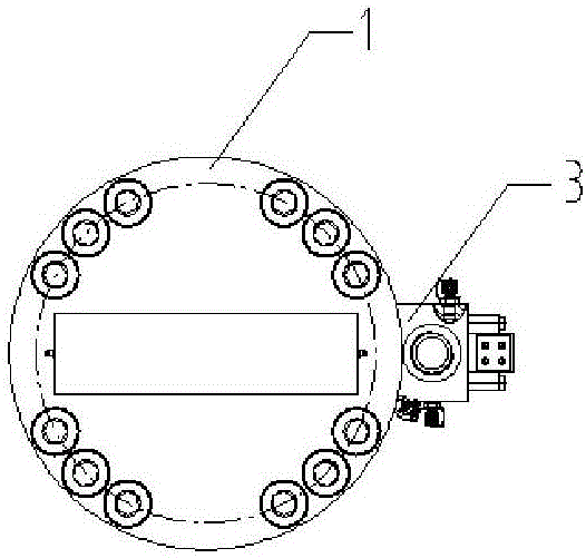
[0004] In order to solve the above-mentioned existing problems, the present invention provides a mechanical-hydraulic double safety locking hydraulic cylinder, which solves the problem of easy jamming, cylinder pulling, limitation of the operating position of the piston rod and hydraulic pressure when the existing hydraulic cylinder is mechanically locked and positioned. The stability is not enough when locking, and the piston is prone to defects such as slippage. The specific plan is as follows:

Method used


Image

  • Mechanical-hydraulic double security locking hydraulic cylinder
  • Mechanical-hydraulic double security locking hydraulic cylinder
  • Mechanical-hydraulic double security locking hydraulic cylinder

Examples


Embodiment Construction

[0033] In order to describe the technical content, structural features, goals and effects of the present invention in detail, the following examples are given to describe the embodiments in conjunction with the accompanying drawings.

[0034] In describing the present invention, it is to be understood that the terms "central", "longitudinal", "transverse", "front", "rear", "left", "right", "vertical", "horizontal", The orientations or positional relationships indicated by "top", "bottom", "inner", "outer", etc. are based on the orientations or positional relationships shown in the drawings, and are only for the convenience of describing the present invention and simplifying the description, rather than indicating or implying The devices or elements referred to must have a specific orientation, be constructed and operate in a specific orientation, and therefore should not be construed as limiting the scope of the invention.

[0035] see Figure 1-5As shown, the present inventi...


PUM


Abstract

The invention discloses a mechanical-hydraulic double security locking hydraulic cylinder which comprises a cylinder body, a piston and a piston rod, wherein the piston and the piston rod are arranged in the cylinder body. A locking cavity is formed in one end of a rodless cavity of the cylinder body and internally provided with a mechanical locking mechanism. A first oil hole and a second oil hole are separately formed in the portions, corresponding to the top and the bottom of the mechanical locking mechanism, of the side wall of the cylinder body. A third oil hole is formed in the portion, corresponding to the extreme movement position of the piston towards the non-locking-cavity end, of the side wall of the cylinder body. The first oil hole, the second oil hole and the third oil hole all communicate with an oil supply pipeline. A hydraulic locking element is arranged outside the third oil hole. The hydraulic cylinder comprises the mechanical locking mechanism and a hydraulic locking protective device, the mechanical locking mechanism can only conduct locking when the piston rod moves to a fixed position, and the hydraulic locking device can conduct locking no matter where the piston rod is located, and in the situation of sudden decompression of the pipeline (such as pipeline burst), when the mechanical locking mechanism is powerless, the hydraulic locking device can respond immediately, mechanical-hydraulic double security is achieved, and malfunction is avoided.

Description

technical field [0001] The invention relates to a mechanical hydraulic device, in particular to a mechanical-hydraulic double safety locking hydraulic cylinder. Background technique [0002] The hydraulic cylinder is a hydraulic actuator that converts hydraulic energy into mechanical energy and performs linear reciprocating motion (or swing motion). It has a simple structure and reliable operation. Since the hydraulic cylinder is an actuator that drives and bears a large load, it is usually required to be able to withstand the external load stably for a long time without any displacement when the movement stops, that is, it needs to have a locking and positioning function without "soft legs". Even under the condition that the hydraulic cylinder loses its power source (hydraulic station), as long as the locking function is not unlocked, no matter how the external load acts, the hydraulic cylinder will not move, which plays a role of safety protection. [0003] At present, th...

Claims


Application Information

Patent Timeline
IPC IPC(8): F15B15/14F15B15/26
CPCF15B15/1423F15B15/264F15B2015/268
Inventor 马晓明许威清钟安国
Owner 北京冶自欧博科技发展有限公司
Learn More