
Wire electric discharge machine operating with constant inter-pole distance

A technology of wire electric discharge machine and processing gap, which is applied to metal processing equipment, electric processing equipment, circuits, etc., and can solve the problem that the average continuous number of short-circuit pulses is not related to the processing gap distance

Active Publication Date: 2017-03-08
FANUC LTD
View PDF6 Cites 8 Cited by
  • Summary
  • Abstract
  • Description
  • Claims
  • Application Information

AI Technical Summary

Problems solved by technology

However, the average consecutive number of short-circuit pulses is not related to the machining gap distance

Method used


Image

  • Wire electric discharge machine operating with constant inter-pole distance
  • Wire electric discharge machine operating with constant inter-pole distance
  • Wire electric discharge machine operating with constant inter-pole distance

Examples


Embodiment Construction

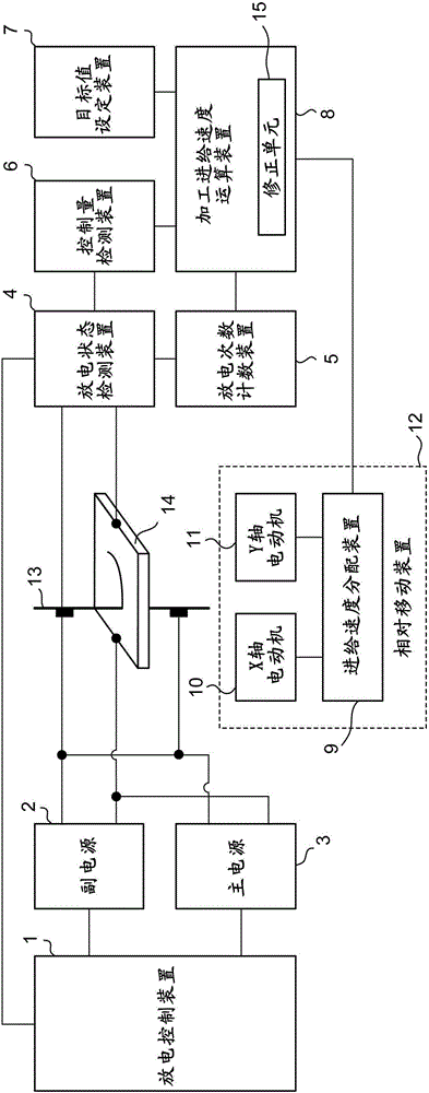
[0029] below, with Figure 1 Embodiments of the present invention will be described together.

[0030] figure 1 It is a block diagram for explaining the wire electric discharge machine of the embodiment of the present invention. The discharge control device 1 instructs the auxiliary power supply 2 and the main power supply 3 to operate according to a predetermined order, and the auxiliary power supply 2 and the main power supply 3 turn on the semiconductor switch based on the instruction to discharge the discharge to the machining gap (the gap formed between the wire electrode 13 and the workpiece 14). ) to supply electrical energy.

[0031] Initially, a predetermined voltage is applied to the processing gap through the auxiliary power supply 2 with high output impedance, and the power supply is switched when a discharge occurs, and a predetermined current is supplied to the processing gap through the main power supply 3 with low output impedance to melt and remove the workp...


PUM


Abstract

In a wire electric discharge machine of the present invention, a control variable detection apparatus is an inter-pole voltage detection apparatus and detects an average inter-pole voltage as a control variable correlating with an inter-pole distance. The wire electric discharge machine comprises a machining feed speed calculation apparatus determining a machining feed speed on the basis of a deviation between target voltage set by a target value setting apparatus and the average inter-pole voltage so as to eliminate the deviation. The wire electric discharge machine further comprises a feed speed distribution apparatus and a relative movement apparatus. The inter-pole distance can be kept constant by the relative movement of a wire electrode and a workpiece made on the basis of a command of thus determined machining feed speed.

Description

technical field [0001] The present invention relates to a wire electric discharge machine, in particular to a wire electric discharge machine which keeps the machining gap distance constant. Background technique [0002] A wire electrical discharge machine is a device that generates electrical discharge in the machining gap formed by the wire electrode and the workpiece to perform machining. In wire electrical discharge machining, machining is performed while maintaining the machining gap at a small distance suitable for electric discharge (machining gap distance), but in order to obtain high-precision machining results, it is necessary to keep the machining gap constant. [0003] In order to keep the machining gap distance constant, the machining gap distance can be detected as the control amount, and the operation amount can be adjusted through feedback control such as proportional control, so that the control amount is close to the predetermined target value. As the oper...

Claims


Application Information

Patent Timeline
Patent Type & Authority Applications(China)
IPC IPC(8): B23H1/02B23H7/20
CPCB23H1/02B23H7/20B23H1/024B23H7/02B23H7/16G05B2219/45043B23H7/30B23H7/32B23H11/00B23H7/065B23H7/04B23H7/18
Inventor 川原章义中岛廉夫
Owner FANUC LTD
Learn More