
Equipment for carding or carding machines

A carding machine and carding machine technology, used in fiber processing, deburring devices, textiles and papermaking, etc., can solve the problems of export and heat loss, and achieve the effect of reducing cooling effect and small deformation.

Inactive Publication Date: 2018-11-09
TRUETZSCHLER GMBH & CO KG
View PDF11 Cites 0 Cited by
  • Summary
  • Abstract
  • Description
  • Claims
  • Application Information

AI Technical Summary

Problems solved by technology

In this case, the thermal insulation extends over the entire height of the rear of the cover, wherein the heat cannot be dissipated via the insulating part below the rear of the cover

Method used


Image

  • Equipment for carding or carding machines
  • Equipment for carding or carding machines
  • Equipment for carding or carding machines

Examples


Embodiment Construction

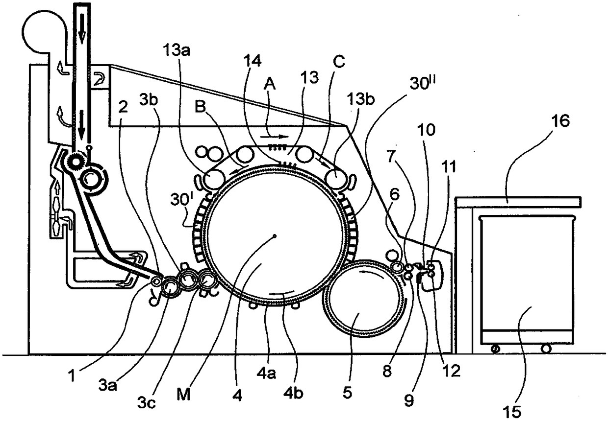
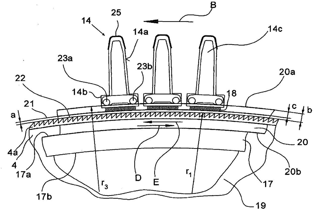
[0019] figure 1 Shown is a card, for example a Truetzschler card TC, which has a feed roller 1, a feed table 2, licker-in covers 3a, 3b, 3c, a cylinder 4, a doffer 5, a stripping Roller 6, pressure rollers 7, 8, web forming guide unit 9, fiber web collection bell mouth 10, separation rollers 11, 12, revolving cover plate 13 with cover plate turning guide rollers 13a, 13b and cover plate rod 14, bar Barrel 15 and coiler 16. The direction of rotation of the rollers is shown with curved arrows. Mark the middle point (axis) of cylinder 4 with M. 4a shows the card clothing and 4b shows the direction of rotation of the cylinder 4 . The direction of rotation of the revolving flat 13 in the carding position is marked with B and the return direction of the flat bar 14 with C, the functional elements with 30 ′, 30 ″ and the flat deflection guide rollers with 13 a and 13 b. Arrow A Mark the working direction.

[0020] according to figure 2 , on each side of the carding machine the...


PUM


Abstract

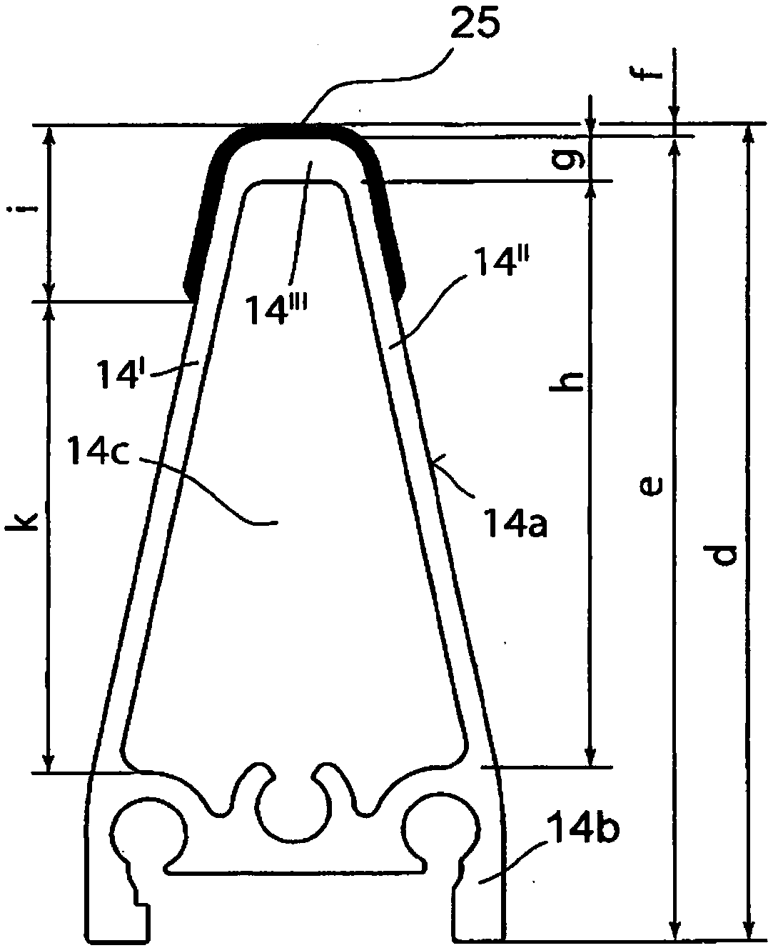
The invention relates to a device on a carder or carding machine on which at least one working and / or cover element of a covered roller is arranged at a distance and extends over the entire width of the roller. Said element comprises an elongate support member having a base part and a rear part with two lateral walls, the rear part being heat insulated on the outward facing surfaces. The base part, which faces the roller, absorbs the operational heat and the rear part facing away from the roller is in contact with ambient air. So that the working and / or cover element, i.e. the cover bar, when in operation, remains dimensionally stable even under the effect of heat, the heat insulation is provided in the upper region of the rear part and said upper region of the rear part comprises the upper surface and one part of both longitudinally aligned lateral walls of the rear part.

Description

technical field [0001] The invention relates to a device on a carding machine or carding machine, in which at least one working element and / or covering element is situated at a distance from a covered roll and extends over the entire width of the roll, said working element And / or the covering element has an elongated carrier comprising a foot and a back with two side walls and equipped with thermal insulation on its outwardly directed surface. Background technique [0002] In today's high-efficiency cards, the heating of the components and the associated change of the spacing of the components are becoming more and more important. Therefore, the same is true for the distance between the cylinder and the flat bar. In order to be able to achieve good quality with maximum throughput, the spacing must be kept as constant as possible. However, the continuous increase in the throughput of the new card generation also leads to a more pronounced difference between the cold-adjuste...

Claims


Application Information

Patent Timeline
Patent Type & Authority Patents(China)
IPC IPC(8): D01G15/24
CPCD01G15/24
Inventor 罗伯特·托本乌尔里希·弗哈特
Owner TRUETZSCHLER GMBH & CO KG
Learn More