Door control device and elevator device
A door control and door panel technology, used in elevators, transportation and packaging in buildings, etc., can solve problems such as the drop of current flowing through the motor, and achieve the effect of suppressing vibration and smooth opening and closing.
- Summary
- Abstract
- Description
- Claims
- Application Information
AI Technical Summary
Problems solved by technology
Method used
Image
Examples
Embodiment approach 1
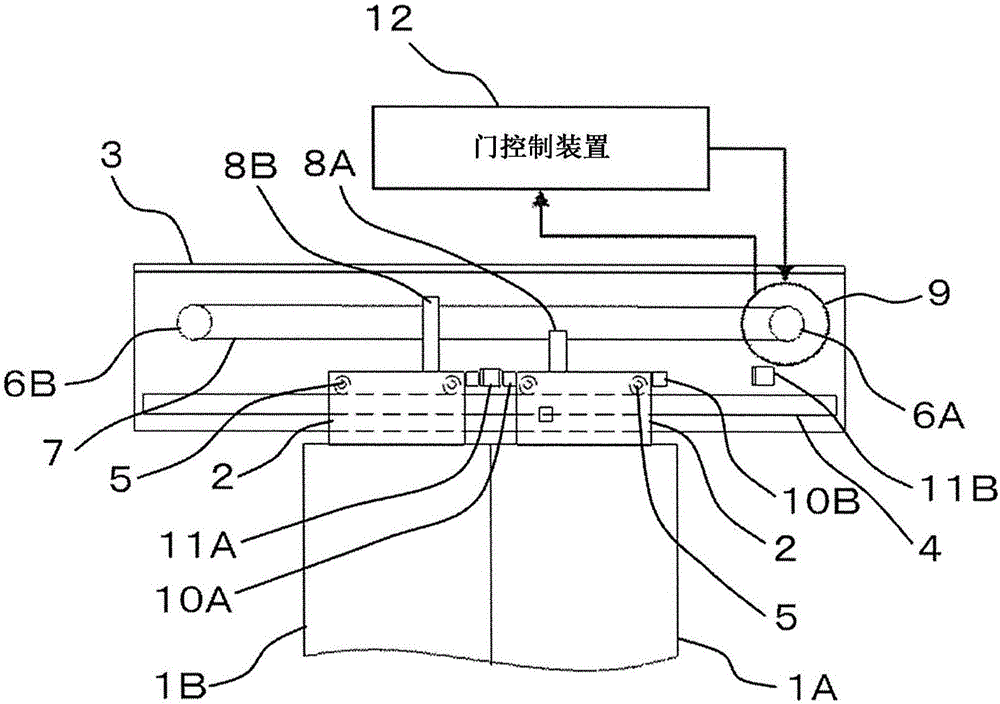
[0028] First, the structure of the door apparatus in Embodiment 1 of this invention is demonstrated. figure 1 It is an overall schematic diagram showing the structure of the door apparatus according to Embodiment 1 of the present invention. figure 1 Shown is a door arrangement that is used, for example, as a door of an elevator installation.
[0029] exist figure 1 Among them, the door device 1 has: door panels 1A, 1B, which open and close the entrance and exit of the elevator car; hangers 2, which are installed on the upper ends of the door panels 1A, 1B; At the upper edge of the entrance and exit; and the guide rail 4 is arranged on the beam 3 so that the long side is along the horizontal direction. The hanger 2 is provided with a plurality of hanging wheels 5, and the hanging wheels 5 are placed on the guide rail 4, and the hanging wheels 5 move along the guide rail 4, thereby guiding the horizontal movement of the hanger 2, that is, guiding the opening of the door panels...
Embodiment approach 2
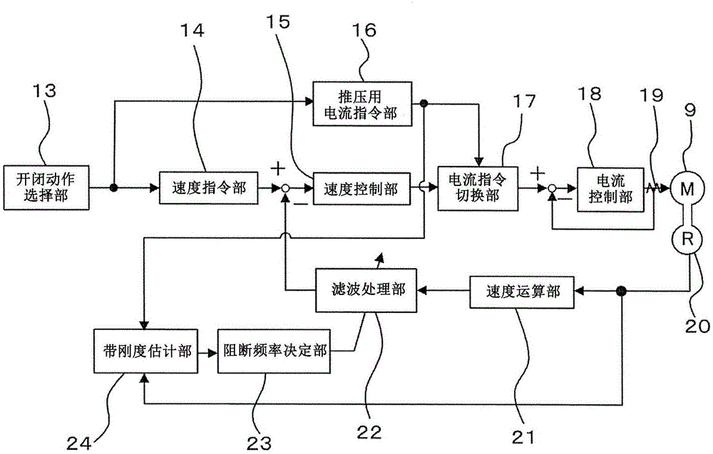
[0098] Figure 6 It is a control block diagram showing the door control device according to Embodiment 2 of the present invention. exist Figure 6 , marked with figure 2 Parts with the same reference numerals represent the same or corresponding structures, and description thereof will be omitted. Figure 6Similar to the door control device of Embodiment 1, the door control device is configured such that the belt stiffness is estimated during the pushing operation, the frequency of the natural vibration of the door is calculated, and the frequency of the natural vibration is removed from the detected value of the moving speed of the door panel by filter processing. composition, thereby achieving smooth door opening and closing. The difference from Embodiment 1 of the present invention is that the belt stiffness is estimated with higher accuracy using the initial tension value of the belt. Hereinafter, differences from Embodiment 1 will be described, and descriptions of the...
Embodiment approach 3
[0117] Figure 7 It is a control block diagram showing the door control device according to Embodiment 3 of the present invention. exist Figure 7 , marked with figure 2 Parts with the same reference numerals represent the same or corresponding structures, and description thereof will be omitted. Figure 7 The door control device has a different structure from the door control device of Embodiment 1. When the opening and closing operation starts, the belt stiffness is estimated to calculate the frequency of the natural vibration of the door characteristics, and the natural vibration frequency is removed from the detected value of the motor rotation speed by filtering. The frequency component of the vibration enables smooth door opening and closing.
[0118] Such as Figure 7 As shown, the door control device 12 according to Embodiment 3 of the present invention is configured to have a current command limiting unit 26 for inputting an operation command from the opening and...
PUM
 Abstract
Description
Claims
Application Information
 - Generate Ideas
- Intellectual Property
- Life Sciences
- Materials
- Tech Scout
- Unparalleled Data Quality
- Higher Quality Content
- 60% Fewer Hallucinations
Browse by: Latest US Patents, China's latest patents, Technical Efficacy Thesaurus, Application Domain, Technology Topic, Popular Technical Reports.
© 2025 PatSnap. All rights reserved.Legal|Privacy policy|Modern Slavery Act Transparency Statement|Sitemap|About US| Contact US: help@patsnap.com


