
Drive unit

A drive unit and drive shaft technology, applied in the direction of electrical components, electric components, transmissions, etc., can solve the problems of interference, axial support is no longer possible, etc., and achieve the effect of great flexibility

Active Publication Date: 2017-02-22
ROBERT BOSCH GMBH
View PDF5 Cites 0 Cited by
  • Summary
  • Abstract
  • Description
  • Claims
  • Application Information

AI Technical Summary

Problems solved by technology

Furthermore, the space required for receiving the third bearing element limits the installation space or the possibility of axial support for the end region of the drive shaft or makes such an axial support no longer possible.
Furthermore, it is considered to be particularly disadvantageous that in the radial gap between the periphery of the drive shaft and the third bearing element, typically due to structural component tolerances, the peripheral surface of the drive shaft Periodic touches or stops at the support elements, which can be perceived as disturbing noises

Method used


Image

  • Drive unit
  • Drive unit
  • Drive unit

Examples


Embodiment Construction

[0037] Identical elements or elements with the same function are provided with the same reference symbols in the figures.

[0038] exist figure 1 The basic structure of a drive unit 100 according to the invention, as it is used as a component of a convenience drive in a motor vehicle, is shown in a very simplified form. A convenience drive is to be understood within the scope of the present invention as an example and without limitation a window regulator drive, a sliding sunroof drive, a seat adjustment drive or the like.

[0039] The drive unit 100 has a drive motor 1 designed as an electric motor with a drive shaft 2 protruding from a housing of the drive motor 1 . The drive shaft 2 of the drive motor 1 is mounted on both sides of the drive motor 1 in first and second bearing elements 3 , 4 , which are preferably designed as ball bearings or slide bearings. exist figure 1 In the embodiment shown in, the two supporting elements 3, 4 are housed or arranged respectively in ...


PUM


Abstract

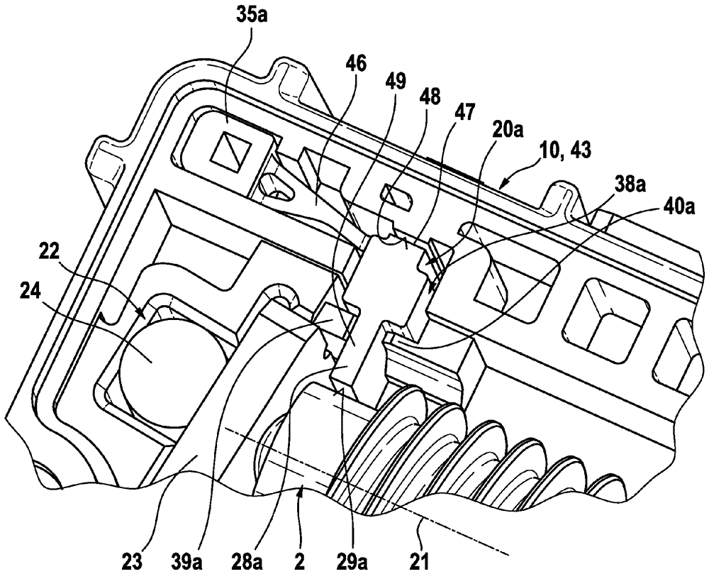
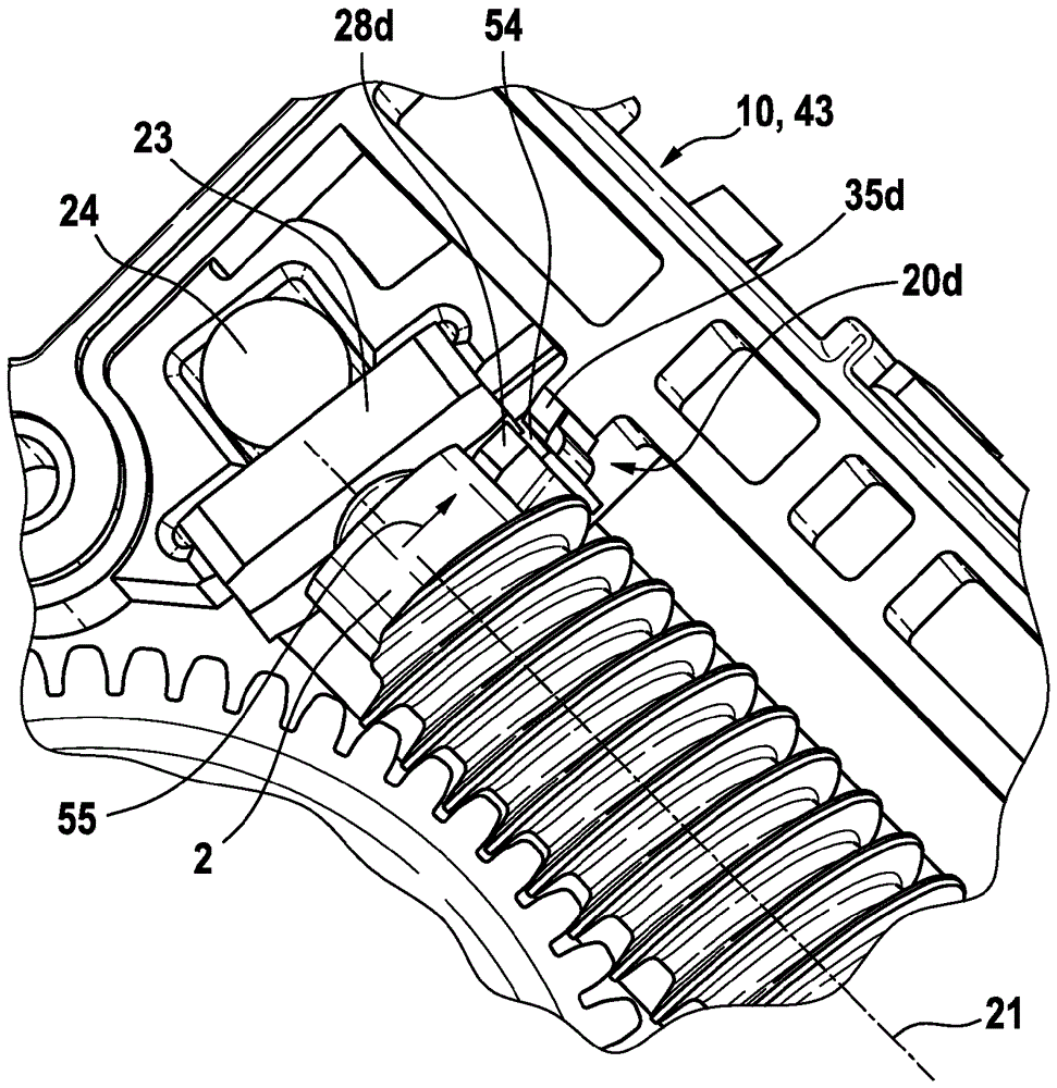
The invention relates to a drive unit (100), with a bearing device (50) for a drive motor (1) which interacts with a gearing element (13) via a drive shaft (2) which is supported at multiple points, with a first bearing element (3) which is arranged on that side of the drive motor (1) which is opposite the gearing element (13), a second bearing element (4) which is arranged between the drive motor (1) and the gearing element (13), and a third bearing element (20; 20a to 20h) which is arranged on that side of the gearing element (13) which faces away from the drive motor (1), wherein the third bearing element (20; 20a to 20h) is arranged movably in a direction perpendicular to the longitudinal axis (21) of the drive shaft (2), and wherein the third bearing element (20; 20a to 20h) is accommodated in a receptacle (38; 38a; 66) of a gearbox (10).

Description

technical field [0001] The invention relates to a drive unit according to the preamble of claim 1 . Background technique [0002] Such a drive unit is known from DE 10 2010 064 295 A1 of the applicant. Known drive units are components of convenience drives in motor vehicles, such as, for example, window regulator drives, sliding sunroof drives, seat adjustment drives. In particular known drive units have a first and a second bearing element on both sides of the drive motor for bearing the drive shaft. The drive shaft interacts with a counter-tooth of a drive wheel designed as a spur gear with a worm gear. On the side of the transmission wheel facing away from the drive motor, a third bearing element is arranged for absorbing or supporting forces acting transversely to the longitudinal axis of the drive shaft, which force causes the offset of the drive shaft described above. For this purpose, the known drive unit or its third bearing element has a section which surrounds ...

Claims


Application Information

Patent Timeline
Patent Type & Authority Applications(China)
IPC IPC(8): H02K7/116H02K7/08F16C27/02F16H57/021F16C19/54F16H55/24
CPCF16C19/54F16C27/02F16H55/24F16H57/021H02K7/08H02K7/1166F16H57/039F16H2057/0213H02K7/081F16H1/16
Inventor G.肖尔普P.施托伊尔S.赖希曼
Owner ROBERT BOSCH GMBH
Learn More