Use of prechambers with dual fuel source engines

A pre-combustion chamber and engine technology, which is applied to combustion engines, internal combustion piston engines, engine components, etc., and can solve problems such as low compression ratio and reduced efficiency

Inactive Publication Date: 2017-02-22
WOODWARD GOVERNOR CO
View PDF10 Cites 10 Cited by
  • Summary
  • Abstract
  • Description
  • Claims
  • Application Information

AI Technical Summary

Problems solved by technology

Therefore, a dual fuel engine with a lower compression ratio for natural gas operation will have reduced efficiency during diesel operation

Method used


Image

  • Use of prechambers with dual fuel source engines
  • Use of prechambers with dual fuel source engines
  • Use of prechambers with dual fuel source engines

Examples


Embodiment Construction

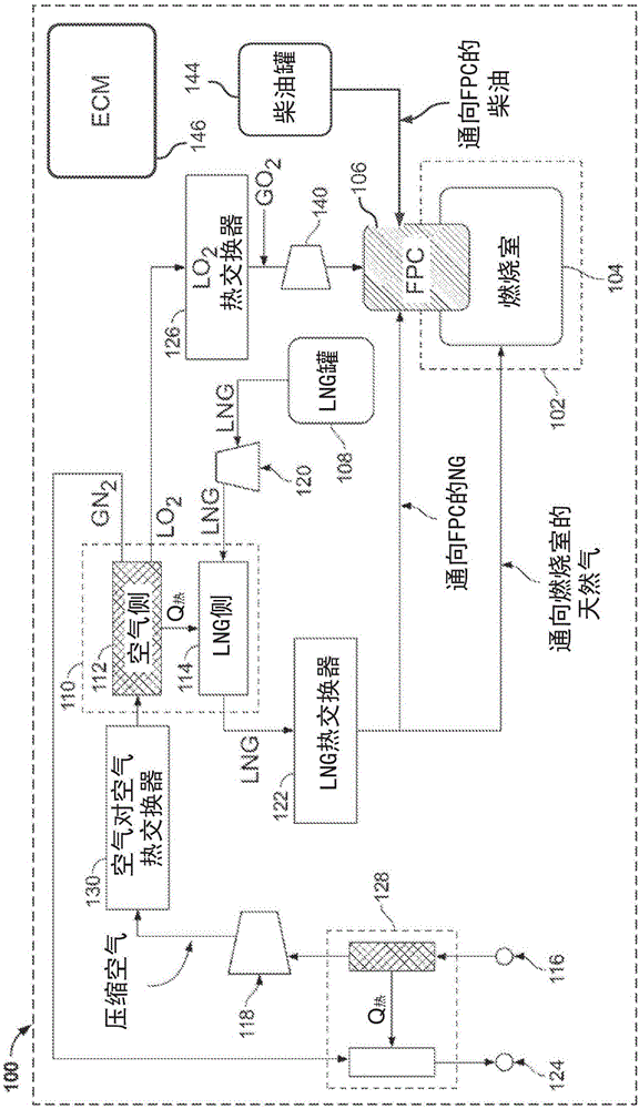
[0033] Figure 1A An example engine 102 is depicted with engine system 100 . The example engine system 100 includes a system that supplies oxygen to the engine 102 . The example engine 102 is a reciprocating piston engine that uses natural gas as fuel, although other engine configurations are within the contemplation of the present invention. Engine system 100 may be incorporated into a skid carrying or associated with engine 102 or a vehicle that may or may not be powered by engine 102 . The engine 102 includes one or more combustors 104 (one shown), each having a feed pre-combustor (FPC) 106 , fed with one or more of liquid fuel, gaseous fuel, and oxygen. In some cases, FPC 106 takes the form of an FPC igniter (eg, a spark plug, laser igniter, hot surface, hot gas, and / or other type of igniter). However, other configurations are also within the contemplation of the present invention.

[0034] The example FPC 106 is configured to receive and ignite one or more gaseous fuel...


PUM


Abstract

A system has an engine. The engine has a combustion chamber, a pre-combustion chamber apart from the combustion chamber, and an opening spanning between the combustion chamber and the pre-combustion chamber. The engine also has a first fuel supply system adapted to supply liquid fuel to the pre-combustion chamber and a second fuel supply system adapted to supply a second, different fuel to the combustion chamber. In certain instances, an oxygen supply system supplies oxygen into the prechamber.

Description

[0001] priority statement [0002] This application claims priority to US Patent Application No. 14 / 215,450, filed March 17, 2014, which is hereby incorporated by reference in its entirety. Background technique [0003] There is an urgent need to operate natural gas engines at leaner air / fuel ratios to achieve higher power density, improved thermal efficiency and low nitrogen oxide (NOx) emissions. As the mixture becomes leaner, the burden on the ignition system increases. Pre-chamber spark plug technology is an effective way to provide reliable ignition, even with a homogeneous lean mixture in the master cylinder. Reliable combustion in the pre-chamber plug generates the necessary pressure to drive turbulent jet combustion in the main combustion chamber. However, such systems have limitations beyond which the air / fuel ratio is too lean to achieve reliable combustion in the pre-chamber as well as in the main chamber. To overcome these limitations, several manufacturers prod...

Claims


Application Information

Patent Timeline
Patent Type & Authority Applications(China)
IPC IPC(8): F02M37/00F02B19/10F02P13/00F02D19/08F02D41/00
CPCF02B19/10F02B19/1023F02B19/1057F02B19/108F02D19/08F02D41/0027F02M37/0064F02P13/00F02B2201/064F02B19/1085F02B19/12F02B19/18F02M25/10F02D41/0025F02D41/403F02B19/00Y02T10/12Y02T10/30
Inventor M·B·莱利G·J·汉普森D·切拉
Owner WOODWARD GOVERNOR CO
Why Eureka
Try Eureka