Actuating device for motor vehicle locks

A technology for an actuating device and a motor vehicle, which is applied in the field of actuating devices and can solve the problems of reducing operating comfort and improving force consumption.

Active Publication Date: 2019-10-29
KIEKERT AG
View PDF7 Cites 0 Cited by
  • Summary
  • Abstract
  • Description
  • Claims
  • Application Information

AI Technical Summary

Problems solved by technology

Increased force consumption due to moving inertial mass in case of mechanical opening
This reduces operating comfort

Method used


Image

  • Actuating device for motor vehicle locks
  • Actuating device for motor vehicle locks
  • Actuating device for motor vehicle locks

Examples


Embodiment Construction

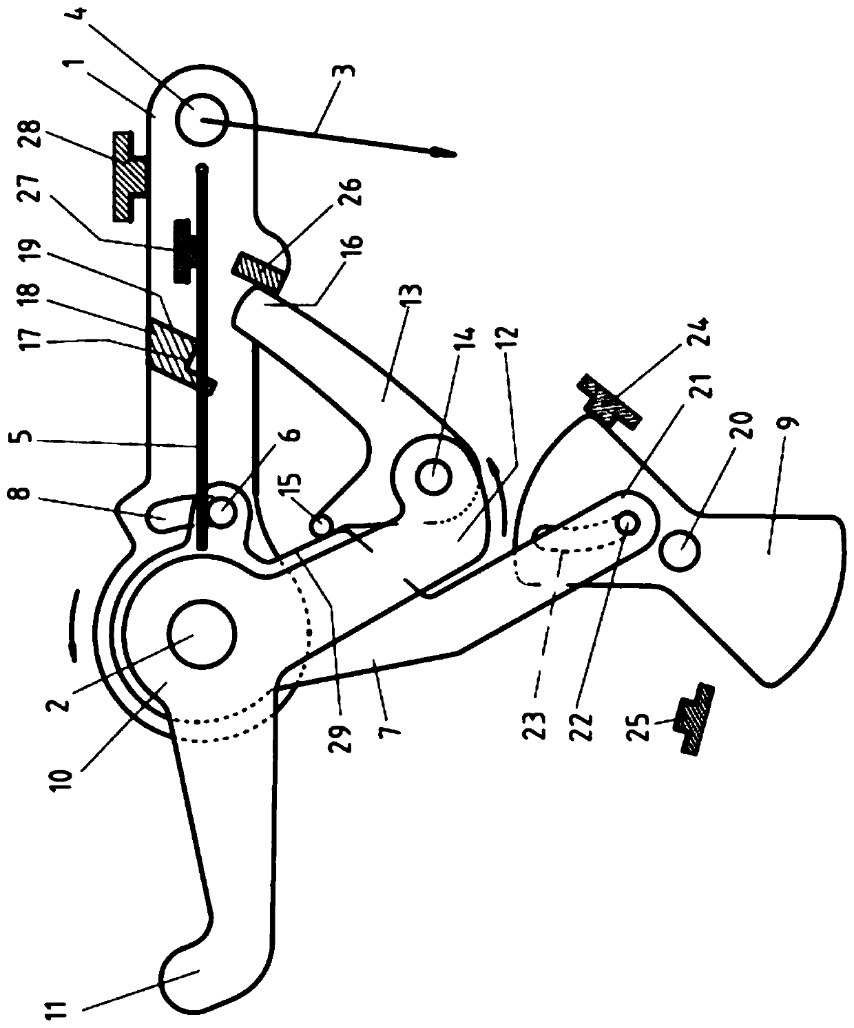
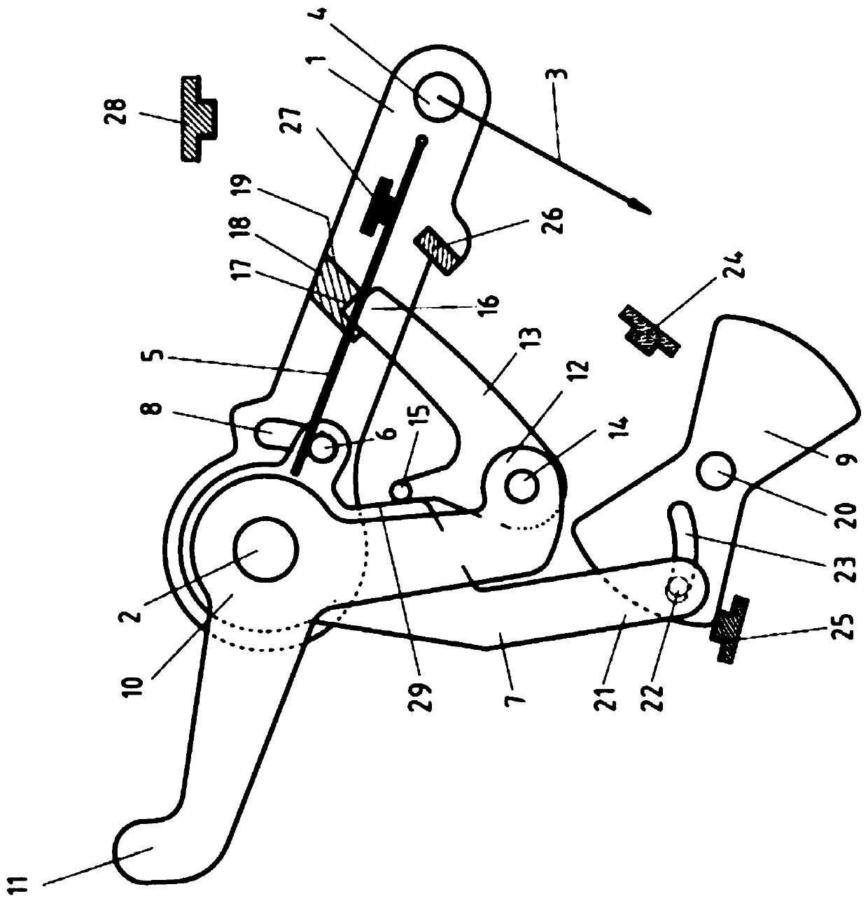
[0028] figure 1 The mechanism of the actuating device for unlocking or opening the not shown locking device is shown, and in particular in the initial position in which the actuating device is not actuated. The mechanism comprises an outer actuating lever 1 which is fixed in a rotatable manner by means of a shaft 2 to a not shown locking plate or to the housing of the actuating device. At the same time, the locking plate or the housing can be a part of the lock (not shown) including the locking device.

[0029] The outer actuating lever 1 is connected to an outer door handle, not shown, via a Bowden cable 3, a cable or via a guide rod. The free end of the outer actuating rod 1 has a fastening element 4 for a cable, guide rod or Bowden cable 3 . If the handle is actuated, the outer actuating lever 1 pivots in clockwise direction about the axis 2 by means of a cable, guide rod or Bowden cable 3 .

[0030]One end of the leaf spring 5 is fixed adjacent to the fixing part 4 on t...


PUM


Abstract

The invention relates to an actuating device for opening a door or flap, comprising a movably supported inertial mass (7, 9) for avoiding unintentional opening of the door or flap in the event that a specified acceleration is exceeded. Levers are provided for moving the inertial mass (7, 9). When the inertial mass (7, 9) is moved out of an initial position of the inertial mass, the lever ratios change in such a way that the force progression is thereby promoted. In the event of a crash, the opening of a door or flap is avoided by means of the actuating device. The actuating device can nevertheless be actuated relatively comfortably with low expenditure of energy.

Description

technical field [0001] The invention relates to an actuating device for a lock of a door or hatch of a motor vehicle. Such a lock has a locking device comprising a rotary locking fork and a locking pawl for locking the rotary locking fork in the locking position, and the locking device optionally also includes a locking pawl for locking the locking pawl in its locking position in the deadlock lever. The actuating device serves to open the door or hatch and thus enables unlocking of the locking device. By actuating the actuating device, the locking pawl is moved out of its locking position and, if necessary, the locking lever is moved out of its locking position and finally the locking device is opened. After this the door or hatch can be opened. Background technique [0002] The actuating device usually has a release lever, which is actuated in order to open or unlock the locking device. Such a release lever is typically connected indirectly or directly to the handle of ...

Claims


Application Information

Patent Timeline
Patent Type & Authority Patents(China)
IPC IPC(8): E05B77/06
CPCE05B77/06E05B77/36E05B77/38Y10S292/22Y10T292/08Y10T292/57
Inventor C·特普费尔T·松嫩沙因
Owner KIEKERT AG
Why Eureka
Try Eureka